On this page
This information is for the assistance of people who intend to construct an electrically powered passenger car or light commercial vehicle. It applies to individually constructed vehicles (ICVs) that are to be originally manufactured for electric drive and to vehicles that are to be converted from petrol or diesel operation.
People who want to build a complete vehicle should also refer to the Requirements for individually constructed vehicles, which contain the general requirements that must be met by all vehicles.
Vehicle standards approval
Before starting construction of an electric vehicle either Apply to modify a light vehicle or Apply to build an individually constructed vehicle.
Apply to modify a light vehicle
Apply to build an individually constructed vehicle
Applications are assessed by the Department for Infrastructure and Transport (DIT) Vehicle Standards and if approved you will receive a statement of requirements which will specify the modifications and any conditions that may apply. The vehicle will be required to be presented for a roadworthy inspection and identification inspection, prior to registration.
For the vehicle to be driven to the place of inspection it must be covered by a trade plate or alternatively an unregistered vehicle permit.
Apply for an unregistered vehicle permit
Engineering certification
Both converted vehicles and newly built vehicles must be certified as continuing to comply with all the applicable Australian Design Rules (ADRs). This certification must be done by a suitably experienced light vehicle engineering signatory recognised by DIT.
Alternatively, another suitably experienced engineer may certify the vehicle by prior arrangement with Vehicle Standards.
They will then guide you through the various requirements and approve your designs along the way. When your conversion or construction is completed, this engineer must inspect your work and write a report which you must take with you to the place of inspection. The engineer should also email the engineering assessment report to Vehicle Standards at least 2 weeks before the inspection date.
Australian Design Rules
A modified vehicle is required by law to continue to comply with the Australian Design Rules to which it was originally constructed, or later versions, except as allowed for in the Road Traffic (Light Vehicle Standards) Rules 2018.
A newly built vehicle is required by law to comply with the Australian Design Rules current at the time of its construction
The ADRs are contained in:
- the Australian Design Rules for Motor Vehicle Safety (Second Edition) covering vehicles manufactured on or after 1 January 1969 to 30 June 1988
- the Australian Design Rules for Motor Vehicles and Trailers (Third Edition) covering vehicles manufactured on or after 1 July 1988.
The applicability of each ADR is based on the date of manufacture and the category of the vehicle. Each ADR has an applicability table that specifies this information. The applicable ADRs are individually listed on the compliance plate of Second Edition ADR vehicles. For Third Edition ADR vehicles, the compliance plate contains the vehicle category and the date of manufacture, from which the applicable ADRs can be determined.
The different ADR versions are numbered in two different formats:
- ADR 4 and ADR 4A in the Second Edition
- ADR 4/00 and ADR 4/01 in the Third Edition.
Note: ADRs are subject to change and therefore builders and modifiers must refer to the most recent version of the applicable ADR prior to commencing any work.
The systems that may be affected by an electric drive conversion are:
- Seat anchorages (ADR 3/...), seatbelt anchorages (ADR 5/...), and child restraint anchorages (ADR 34/...) - any structural alteration made in the vicinity of the seat or seatbelt mountings, or the child restraint anchorages, may reduce their strength.
- Occupant protection (ADRs 10/..., 21/..., 69/... and 73/...) - structural alterations, particularly about the forward portion of the vehicle, the removal of the original engine, or large increases in vehicle mass made by the addition of the traction batteries and motors, may affect the energy absorption characteristics of the vehicle structure, instrument panel or steering column.
- Demisting of windscreens (ADR 42/...) - the removal of the engine will necessitate the provision of an alternative source of heat for demisting air (or alternative demisting arrangements.) Performance, comparable to the original demisting system must be maintained.
- Motor vehicle noise (ADRs 28/... and 83/...) - in general, electric vehicles are quieter than those fitted with internal combustion engines. Alternative gearboxes, chain drives, and some electric control apparatus may increase noise levels and attention must be given to ensuring that this does not result in excessive external noise.
- Emissions (ADRs 26, 27, 30/..., 37/... and 79/...) - the emission requirements do not apply to purely electric vehicles; however, hybrid vehicles (ie battery vehicles with an internal combustion engine powering an onboard generator) will be expected to comply with the relevant emissions ADRs.
- Braking systems (ADRs 31/... and 35/...) - large increases in vehicle mass, alteration of the centre of gravity, and or removal of the normal vacuum or compressed air source will affect compliance with these rules and it is essential that braking performance be maintained within the limits set out by these rules. The addition of a secondary source of vacuum or compressed air will usually be required. The vehicle must continue to comply with the design rule requirement that vehicles have a brake failure warning lamp that can be tested by turning the ignition switch to the "start" position.
Weight considerations
One problem, which must not be overlooked, is the possibility that some mechanical components of the converted vehicle might become overloaded because of the increase in weight caused by the addition of the traction batteries and motors. This is particularly important with the tyre and axle loadings of converted passenger cars and light commercial vehicles. Check that the strength and fatigue resistance of every component is adequate for its new function, manufacturers can supply advice about these loadings, and bear in mind that a change in weight distribution can overload components (eg front axle) without there necessarily being an increase in the overall weight.
Remember that it is the weight of the laden vehicle that matters. Allow at least 68 kg per passenger, plus 13.6 kg of luggage for each passenger, for a total minimum allowance of 81.6 kg per passenger.
This allowance is the legal minimum. Given the size of the Australian population, it is recommended that the allowance chosen is higher. The intended use of the vehicle should also be considered, a vehicle intended for shopping or as a family runabout will require a higher allowance than a vehicle used purely for commuting.
Brakes and steering
If the original vehicle was fitted with air brakes, vacuum-assisted brakes or power-assisted steering, an alternative source of energy must be fitted. The power and capacity of the new source must be of sufficient capacity to provide efficient functioning of the system and meet all the legal capacity requirements.
Acoustic Vehicle Alerting System (AVAS)
Vehicles converted to electric drive and individually constructed electric vehicles built on or after 01 November 2025 must be fitted with an AVAS system complying with ADR 113 to aid pedestrians and other vulnerable road users in detecting the presence of electric vehicles.
Electrical technical and safety requirements
Electrical definitions
ELV: extra low voltage. Any voltage that never exceeds 60V DC or 25V AC- typically powering electrical items such as lights, horn, and fans.
HAZV: hazardous voltage. Any voltage that may be greater than 60V DC or 25V AC at any time - typically the voltage of the main traction battery pack or the motor drive circuits.
Battery type
There is a significant difference in safety requirements for distinct types of batteries. For the purposes of this document, batteries are divided into two principal types:
Class A: The batteries do not contain spillable liquid and do not discharge gases into the atmosphere during normal operation.
Class B: The batteries contain spillable liquid and or discharge gas during normal operation. As a broad classification, lead-acid flooded batteries are Class B, while Nickel Metal Hydride (NiMH) and Lithium batteries are Class A.
Battery restraint
The batteries that power the vehicle must be fixed in position so that they will not easily break free in a crash and thus create a hazard to the driver, passengers, or other road users. The battery restraint system must withstand at least the following crash accelerations:
- Front-impact - 20 g - ie 20 times the battery weight
- Side impact - 15 g
- Rear impact - 10 g
- Vertical (rollover) impact - 10 g.
Battery restraints must be designed so that during fitting and maintenance operations, either the restraints or any tools required cannot easily provide a short circuit path for the battery terminals or other exposed wiring and connections.
Containment of batteries
All Class B batteries must be fully sealed from the passenger compartment so that the transmission of gases or flames is prevented. The sealed compartment should be made from corrosion-resistant materials, or if this is not practical, lined with corrosion-resistant materials. Fully sealed - ie Class A batteries need not comply with this section.
Any battery system which is sealed and externally vented or contains a water-replenishing device that connects a number of batteries must be designed so that propagation of flame between battery cases cannot occur.
All batteries must be enclosed to provide water resistance and exclusion of foreign objects, to a rating of at least IP2X.
As an additional precaution, a roll-over detection switch should also be considered, especially for vehicles powered by Class B batteries that contain spillable liquid.
Venting of battery compartments - Class B batteries only
The design of the batteries, or battery compartments, must provide for venting directly to the atmosphere of all gases given off by normal battery operation. This is of utmost importance for lead-acid batteries because hydrogen can be given off in quantities sufficient to cause an explosion during recharging. Inlets and outlets for venting must be well separated to prevent exhausting gases from re-entering the compartment. Venting must not exit underneath the vehicle because the accumulation of potentially explosive gasses may occur.
Depending on the battery type and the size of the vents, a forced ventilation system may be required.
Labelling of battery compartments
Some batteries contain chemicals, particularly acids, which may cause a hazard in the event of a crash.
Each battery compartment should be labelled with the appropriate hazard symbols for the battery chemistry in use.
Marking of hazardous voltage components
Electric vehicles usually employ higher voltages than normal internal combustion vehicles and consideration needs to be shown to the safety of the end-user of the vehicle, service personnel, and emergency responders in the event of an accident.
All wiring in the vehicle connected to a HAZV battery pack, either positive or negative, or containing HAZV relative to the chassis of the vehicle, must be coloured orange or sheathed orange even when installed within the orange conduit. A short length of red or black or other colour heath or heat-shrink may be used at the ends of the cables to indicate polarity or other purposes as necessary. For all new wiring, orange-coloured wiring or sheathing or conduit must only be used for HAZV circuits. Original wiring harnesses fitted by the vehicle manufacturer that contains orange wiring do not need to be modified to remove the orange wiring. Red and black wiring colours must be reserved for ELV circuits.
Protection against electric shock
Direct contact with HAZV parts of the vehicle must be prevented either by insulation or by the use of a reliably secured cover that can only be removed with the use of a tool.
In passenger and load compartments of the vehicle, the covers must protect any exposed HAZV components to a protection rating of at least IP4X.
Covers in other areas of the vehicle (including under the bonnet) must protect any exposed HAZV components to a protection rating of at least IP2X.
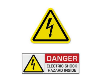
Figure 1. Warning labels - see text for sizing
Covers protecting HAZV parts must have either one of the two warning labels shown in Figure 1 affixed in a conspicuous location. The label must be at least 40 mm in height unless there is not enough space for a label of this size. Where space is restricted, the largest possible warning label having the same message and characters must be used. These warning labels are readily available and comply with AS 1319-1994 Safety signs for the occupational environment.
All HAZV wiring should be located outside the passenger compartment or load space in order to minimise the possibility of contact by the operator or passengers. In places where the placement of electrical wiring in the passenger compartment or load space is unavoidable, the wiring must be contained within a protective housing such as flexible or rigid orange conduit or by an additional double-insulated orange sheath.
Hazardous voltage isolation
Any HAZV traction battery system must be isolated from the chassis of the vehicle, and also from any auxiliary ELV components and wiring. Isolation must be designed such that there is a leakage current of less than 20 mA between any part of the HAZV system and either the chassis or ELV components in the vehicle, measured when the vehicle is at rest.
This requirement means that both the HAZV battery pack positive, and the HAZV battery pack negative, is to be floating relative to the chassis during normal operation, and both are to be treated as HAZV components.
A ground fault detection circuit or device must be used to identify that either the battery pack positive or battery pack negative has come into contact with the chassis or ELV part of the vehicle, and flag this as a fault to the driver or service technician.
Isolation must be checked manually before commencing any work or repairs on the HAZV circuits and any handbook or information prepared to assist the owner should make reference to this precaution.
Hazardous voltage disconnect
The power-on procedure must be applied via a key switch or equivalent. It must not be possible to remove this key in any position that energises the drive train or makes active driving possible.
Disconnection of the traction pack from the rest of the traction circuit must be by a contactor operated by the ignition switch. The ignition switch must be located within easy reach of the driver. The ignition switch must isolate all electrical connections to the power source. It must be operable by direct mechanical action and must not rely on any electrical or electromechanical device.
An inertia switch must be employed to disconnect the traction pack from the rest of the traction circuit in the event of a collision. The inertia switch should be set to the same limit as existing safety systems in the vehicle.
If the vehicle does not have existing safety systems, 10G should be used.
Additional switches may be installed to interrupt the supply to assist the user or repairer of the vehicle. For example, a toggle switch may be installed to enable the driver to shut down the battery supply without resorting to turning off the ignition key, as switching off the ignition will also disable devices such as brake boosters and also potentially lock the steering.
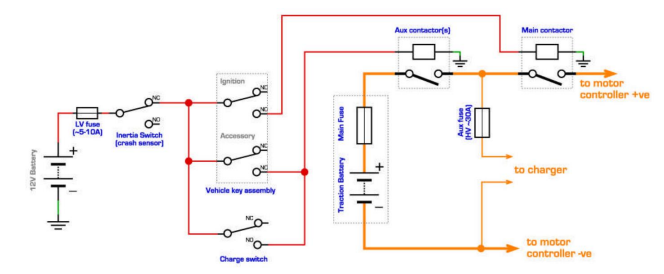
Figure 2. Typical circuit showing ignition switch, battery pack contactors and optional HV disable switch
Hazardous voltage protection device
A battery pack over-current protection device - eg fuse or overload relay/circuit breaker, must be installed in the traction supply circuit. It should be located with the minimum practical length of cable between the battery terminals and the device to minimize the chance of a fault occurring in the unprotected section of the cable. It should be mounted as close as practicable to the battery pack.
Due to the presence of explosive gases, the fuse or other device for a Class B battery pack must be located outside of the battery enclosure unless EX explosion proof rated. The fuse or other device for a Class A battery pack may be located inside the battery enclosure to help minimise the exposed length of the cable.
The over-current protection device must be rated by its manufacturer for use with direct current and at the maximum possible battery voltage. The over-current protection device must have an interrupting rating or breaking capacity which exceeds the maximum possible fault current which may flow – usually the short circuit current of the battery, but possibly the maximum fault current of the traction circuit. If the over-current protection device is a fuse, it should be a high rupture capacity (HRC) type fuse.
Power supply priority - for ELV traction battery pack only
If safety equipment such as lights, brakes, and windscreen wipers use the same power source as the traction motor, these services must be supplied in preference to the traction circuit. The design of any ancillary equipment supply should be such that satisfactory operation of all equipment, particularly brakes and headlights, is available throughout the discharge cycle of the traction batteries.
Auxiliary ELV
An independent auxiliary ELV, nominally 12V, must be used to guarantee the supply of power to safety equipment such as lights, brake boosters, and windscreen wipers in the event of a shutdown of the main battery system in the vehicle. Typically this power supply is a 12V battery. The auxiliary supply must be capable of operating the hazard lights, four-way flashers, at a normal duty cycle, for a minimum period of 20 continuous minutes.
If the auxiliary supply is charged via a DC/DC converter from the main traction battery pack then it must be supplied in preference to the traction circuit, ie the motor should stop working before the headlights. The auxiliary equipment supply must be designed so that the satisfactory operation of all equipment, particularly brakes and headlights, is possible throughout the discharge cycle of the traction batteries.
If the original vehicle was fitted with a brake fluid level and or hand brake (or foot-operated) parking brake indication light(s) on the dashboard, then these must be retained on the modified vehicle.
Vehicle directional control
Vehicles not fitted with a conventional gearbox and using a voltage reversal switch to select reverse drive must be designed so that they cannot be accidentally placed in reverse. This action requires either:
a) A combination of two different actuations - eg a toggle switch with a cover, or a separate reverse enabling switch, or
b) A momentary contact switch that allows the reverse gear to be engaged only when the vehicle is moving with a forward speed of less than 5 km/h. Above this speed, all actions on this switch must be ineffective.
The state of the drive direction - eg forward or neutral or reverse, must be readily identifiable to the driver. This can be achieved by a number of means including labels on or near the direction control device and lamps on the dash.
The vehicle must not be capable of being driven in either direction if the ignition key switch is not in the on position. The drive motor controller or other device control/software may be utilised to achieve this requirement.
The vehicle must not be capable of being driven in either direction if the vehicle is connected to an energy supply network or an off-board charger.
Battery management
For series strings of batteries, some form of charge or balance management should be implemented. The necessity of this requirement will be dependent on the battery chemistry and technology used in the vehicle. This is especially critical with lithium chemistry batteries which must be maintained within strict upper and lower voltage limits and upper and sometimes lower temperature limits. Some form of device to monitor these limits on each individual cell or group of parallel cells should be present.
If a monitoring device is fitted, the monitoring device must be capable of either audibly or visually by means of a flashing lamp or other indicator, warning the driver of an impending disconnect with sufficient time for the driver to safely park the vehicle before disconnection occurs.
Allowance for Australian climatic conditions
To ensure satisfactory service over the range of climatic conditions found in Australia, electric vehicles must be designed for prolonged operation at ambient temperatures ranging from - 10°C to +50°C.
Number plate warning labels
Electric-powered vehicles must be fitted with warning labels according to the vehicle standards Labelling requirements for hydrogen and electric-powered vehicles. This labelling is to assist emergency service responders to identify vehicles powered by electricity and take any necessary precautions when responding.
Alternative standard
The electrical system of the vehicle will be acceptable if it can be shown to comply with the technical requirements of UN ECE Regulation No 100 Uniform Provisions concerning the Approval of Battery Electric Vehicles with Regard to Specific Requirements for the Construction and Functional Safety. It must be noted that such a vehicle is still required to comply with the other ADRs that may be affected by a conversion.
Special notes
Before starting construction of an electric vehicle some knowledge can be gained by reading Australian/New Zealand Standard AS/NZS 3000:2000: Electrical installations (known as the Australian/New Zealand Wiring Rules), in particular, section 7.9 Hazardous Areas. At the time of inspection:
- A copy of the statement of requirements issued by DIT and a copy of the engineer’s report must be produced and retained by the inspecting officer.
- If the vehicle is imported, a copy of the 'Import Approval' issued by the Department of Infrastructure, Transport, Regional Development, Communications and the Arts must be produced to the inspecting officer.
Vehicle Standards reference: MR648.