On this page
This information details the requirements to obtain approval for road use of an individually constructed vehicle (ICV) up to 4.5 tonnes of gross vehicle mass (GVM).
The construction of passenger vehicles is a complex and usually time-consuming project. The Department for Infrastructure and Transport (DIT) aims to ensure that the requirements of Australian Design Rules (ADRs) and Regulations, related to safety and environmental protection are equivalent to production vehicles.
Not only must high-quality components be used, but all components used in the design must be correctly matched to each other to ensure safe operation, performance, and compliance with the relevant standards. The motor vehicle must be considered a complete package.
All requirements of the ADRs and South Australian Road Traffic (Light Vehicle Standards) Rules 2018 are not fully detailed. It is the vehicle constructor’s responsibility to ensure that an ICV complies as fully as possible with the ADRs and the South Australian Road Traffic (Light Vehicle Standards) Rules 2018.
Definition of an ICV
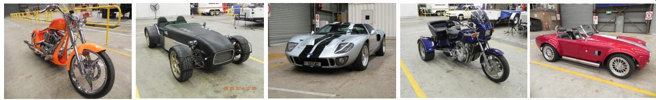
An ICV is a one-off motor vehicle constructed by individuals, including a motorbike and trike, built to an individual plan or design meeting the intent of ADRs applicable at the time of manufacture.
An ICV:
a. is a new vehicle that is not a production vehicle, a modified production vehicle, or a production vehicle that has had the body or chassis replaced
b. will be used only for personal use
c. has its steering not to the left of the centre of its longitudinal axis
d. is not a trailer
e.has been issued with a new Vehicle Identification Number (VIN)
f. has a new body and chassis, but sub-assemblies and components used during construction may be derived from other production vehicles
g. is, but is not required to be, a kit car or a replica of a historic (production) vehicle.
A kit car is a form of ICV, usually built from a partial or complete kit provided by a manufacturer or supplier. Owners are free to assemble the vehicle in a personally customised form, providing they comply with the ICV guidelines and meet the intent of ADRs applicable at the time of manufacture.
If you are constructing more than three (3) vehicles per year, you need to seek advice from DIT Vehicle Standards and the Department of Infrastructure, Transport, Regional Development, Communications, Sport and the Arts.
Such vehicles must be certified by the Department of Infrastructure, Transport, Regional Development, Communications, Sport and the Arts prior to registration.
Engineering requirements
Design and engineer’s responsibility
All aspects of design including compliance with Australian Design Rules, and Regulations, compatibility of the engine with other vehicle components, steering, braking, handling and drivability will remain the responsibility of the light vehicle engineering signatory submitting the engineering report.
Inspection procedure
It is recommended that the vehicle be inspected by the engineer at the following stages:
a. At the completion of the chassis prior to the fitting of the body or any other component which may obstruct inspection of chassis welds etc.
b. At some intermediate stage of construction.
c. After completion of the vehicle but prior to presentation for the full roadworthy inspection by DIT.
Light vehicle engineering signatory's report
All aspects of design and components used must be fully addressed in a report prepared by a light vehicle engineering signatory (LVES).
Letter of conformity
As assurance that the vehicle has been inspected by the light vehicle engineering signatory and the vehicle conforms with the engineering report, a letter of conformity must be submitted prior to the vehicle being inspected by DIT.
The letter of conformity must include:
- name and address of the owner make and type of vehicle
- chassis number or VIN
- engine number
- dates of inspection during construction
- a statement to the effect that the above vehicle has been constructed in accordance with the engineering report number and dated
- signature of the light vehicle engineering signatory, dated and signed.
A list of appropriately qualified and experienced engineers involved in this type of work in South Australia is available from DIT.
Recommended construction and approval process
a. Consult the light vehicle engineering signatory as to the acceptability of the vehicle’s proposed construction and revise if necessary.
b. Obtain confirmation from the engineer that the proposed vehicle will comply with the appropriate ADRs and Regulations. This confirmation usually takes the form of an engineering report and enables the construction of the vehicle to commence, however, see point ‘d.’
c. Complete the Application to build an individually constructed vehicle form and submit it to Vehicle Standards together with the engineering report and any other relevant documentation.
d. If the proposal is accepted then Vehicle Standards will then issue a statement of requirements (SOR). If the proposal is not acceptable or further information is required Vehicle Standards will contact the applicant in writing. This should be done as early in the process as possible because the SOR or Regulation changes may influence the design.
e. Following the completion of construction, the vehicle must undergo inspection and performance testing by the engineering signatory to ensure that the vehicle meets all applicable standards and regulations and to verify that its safe operation on the road is ensured. The results of all performance tests must be recorded and retained by the engineer. The light vehicle engineering signatory must then complete a letter of conformity to confirm that the vehicle has been constructed in accordance with the engineering report.
f. Following the letter of conformity and the receipt of a statement of requirements from Vehicle Standards, the vehicle can be booked in for a full roadworthy inspection. If the vehicle fails inspection, the relevant issues must be addressed and the vehicle submitted for inspection at a later date. When the vehicle passes inspection it can then be registered and will be issued with an Exemption From the Fitting of a Compliance Plate and a South Australian I.D. Label which will identify the vehicle.
Applications
Except for those aspects which can only be determined after construction is completed, the application prepared by the light vehicle engineering signatory and submitted to DIT must give full design details relating to the following.
Engine and driveline
- Engine make, size and number of cylinders
- Any changes from standard specifications
- Power and torque specifications
- Turbocharger or supercharger, if fitted
- Drive-line and differential
- Gearbox and transmission
- Fuel system - ie petrol, diesel, LPG.
Engine selection
Engine power and torque must be compatible with the driveline, structural, and braking components. For details relating to emission control refer to ADR 37/...
Brakes
- System (refer to ADR 31/.. and 42/..)
- Type - ie disc, drum
- Brake balance.
Vehicle braking
Tests to show compliance with ADR 31/.., or equivalent, must be conducted and submitted prior to the presentation of the vehicle for a final inspection.
Refer to the Brake system test procedure or refer to ADR 31/...
Brake balance
Tests to ensure the correct brake balance must be conducted and submitted prior to the presentation of the vehicle for a final inspection.
Wheels and tyres
Size, speed and load ratings, carcass construction (refer to ADR 23/..)
Axels and suspension
- Type and make of axles - front and rear
- Method of attachment
- Strength at 1g braking and 3g bump
- Width of axles between wheel mounting flanges
- Bump clearance
- Ground clearance - refer to ADR 43/..
- Track - front and rear.
Wheel track
The wheel track is the distance measured across an axle between the centre line of the left wheel and the centre line of the right wheel. Where standard axles are used the wheel track will be based on the maximum allowable wheel track for the vehicle for which the axle was designed.
Alternatively, an engineering report showing that the wheel track is within the design capabilities of the components being used and that the track does not have any adverse effect on vehicle handling and/or steering. Where non-standard components are fitted the wheel track will be assessed, determined, and justified by the engineer.
Steering
- Steering geometry
- Steering column - refer to ADR 10/..
- Anti-theft locks - refer to ADR 25/...
Components
Steering components are not permitted to be welded or heat treated unless a detailed engineering report addressing the welding and heat treatment is submitted to DIT.
All newly manufactured steering components must be identified and a full description of manufacture including drawings must be presented, as well as an assessment and statement of suitability by the engineer.
Geometry
Test results of a subjective test that show handling characteristics must be submitted prior to the presentation of the vehicle for a final inspection.
Refer to Lane change manoeuvre test procedures.
In addition, the LVES should show that the vehicle does not demonstrate excessive ‘bump steer’ throughout the operating range of the front suspension.
Chassis or frame
- Style and type
- Material and strength
- Mounting of the body to the chassis or frame
- Beaming and torsional rigidity
- Wheelbase.
Beaming and torsional rigidity
The beaming and torsional rigidity is usually evaluated on the composite chassis or frame and body. An engineering report on the beaming and torsional rigidity of a procedure acceptable to DIT would be required.
Refer to Vehicle structure testing.
Body
- Style and type
- Material
- Position and accessibility of foot controls
- Door strength - refer to ADR 29/..
- Door latches and hinges - refer to ADR2/..
- Mudguards - refer to ADR 42/..
- Engine bonnet - refer to ADR 42/..
- Driver field of view - refer to ADR 42/..
- Primary vision area - refer to ADR 8/..
- External and internal projections - refer to ADR 42/..
- Internal sun visors - refer to ADR 11/..
- Location and visibility of instruments - refer to ADR 18/..
- Instrument panels - refer to ADR 21/...
Body design
It is essential to carefully examine the requirements of the driver's field of view, primary vision area, windscreen wipers, and washers and mudguards when designing the body shell of the vehicle.
Occupant protection
The following ADRs apply to passenger car-type vehicles:
| ADR 69/.. |
Full frontal impact Occupant protection |
| ADR 72/.. |
Dynamic side impact Occupant protection |
| ADR 73/.. |
Offset frontal impact Occupant protection |
ICVs are not required to prove compliance with these ADRs but should be constructed to comply with the intent of these ADRs and offer the best occupant protection possible. See Dynamic occupant protection.
Seats and seatbelts
- Type and number of seats
- Size and height of seats
- Seat anchorages - refer to ADR 3/..
- Seatbelts - refer to ADR 4/..
- Seatbelt anchorage points - refer to ADR 5/..
- Child restraint anchorages - refer to ADR 34/..
- Head restraints - refer to ADR 22/..
- Instructions for the use of ‘Seatbelt Assemblies’ - refer to ADR 4/..
- Instructions for the use of ’Child Restraint Anchorages ‘ - refer to ADR 34/...
Emissions and noise
- ICVs constructed before 31/12/03 must comply with ADR 37/00 Emission Control for Light Vehicles.
- ICVs constructed after 31/12/03 must comply with ADR 37/01 Emission Control for Light Vehicles
- Where satisfactory evidence can be provided that vehicle construction commenced prior to 31/12/03 DIT may accept compliance with ADR 37/00.
- ADR 37/.. includes exhaust emissions, evaporative emissions, crankcase gasses, and petrol filler inlets.
- Diesel engine smoke (refer to ADR 30/..)
- External noise (refer to ADR 28/..).
Glazing and visibility
- Glazing material (refer to ADR 8/..)
- Rear vision mirrors (refer to ADR 14/..)
- Demisting of windscreens (refer to ADR 42/..)
- Windscreen wipers and washers (refer to ADR 42/..)
- Driver field of view (refer to ADR 42/..)
- Primary vision area (refer to ADR 8/..)
- Window tinting – refer to Window tinting
- Centre high-mounted stop lamp (refer to ADR 60/..)
Lamp and signal requirements
- Headlamps (refer to ADR 46/..)
- Front position lamps (refer to ADR 49/..)
- Rear position lamps (refer to ADR 49/..)
- Rear registration plate illuminating device (refer to ADR 48/..)
- Retro-reflectors (refer to ADR 47/..)
- Hazard warning signals (refer to ADR 13..)
- Globes (refer to ADR 51/..)
- Reversing lamps (refer to ADR 1/..)
- Direction indicator lamps (refer to ADR 6/..)
- Centre high-mounted stop lamp (refer to ADR 60..).
General provisions
- Turning circle (refer to ADR 43/..)
- Controls (refer to ADR 42/..)
- Electrical wiring (refer to ADR 42/..)
- Exhaust outlets (refer to ADR 42/..)
- Ventilation (refer to ADR 42/..)
- Reverse gear (refer to ADR 42/..)
- Engine number (refer to ADR 43/..)
- Warning device (refer to ADR 42/..)
- Registration plates and labels (refer to ADR43/..)
- Vehicle identification number (refer to ADR 43/..).
Australian Design Rules
The ADRs have been developed to provide detailed performance specifications for safety standards in vehicles with the objective of reducing:
- the frequency of accidents
- the severity of occupant injury when accidents do occur
- the adverse impact of noise, smoke, and gaseous emissions on the community and the environment.
Components used in constructing an ICV may be taken from a vehicle that complies with the relevant ADRs provided that details of the make, model and date of manufacture of the vehicle concerned are quoted. Items that are not identical to those from a complying vehicle may be accepted subject to an engineering evaluation. Following is a resume of the relevant ADRs. The requirements quoted are only an abbreviation of compliance required for a vehicle to meet the intent of the specific ADRs. Every ICV is required to comply with the intent of the relevant ADRs listed below.
ADR number and title
1/..Reversing Lamps
2/..Side Door Latches & Hinges
3/..Seat Anchorages
4/..Seatbelts
5/..Anchorages for Seatbelts
6/..Direction Indicator Lamps
8/..Safety Glazing Material
10/..Steering Column
11/..Internal Sun Visors
13/..Installation of Lighting & Light-signalling Devices
14/..Rear Vision Mirrors
18/..Instrumentation
21/..Instrument Panel
22/..Head Restraints
23/..Passenger Car Tyres
25/..Anti-Theft Lock
28/..External Noise of Motor Vehicles
29/..Side Door Strength
30/..Diesel Engine Exhaust Smoke Emission
31/..Hydraulic Brake Systems for Passenger Cars
34/..Child Restraint Anchorages and Child Restraint
Anchor Fittings
37/..Emission Control for Light Vehicles
42/..General Safety Requirements
- contains information on the following:
- Bonnet Latching
- Diesel Engines (anti-start locking device)
- Controls
- Electrical Wiring, Connections & Installations
- Exhaust Outlets
- External or Internal Protrusions
- Field of View
- Wheel Guards (Mudguards)
- Brake Tubing & Brake Hose
- Reverse Gear
- Television & Visual Display Units
- Windows & Ventilation
- Warning Devices - Audible
- Demisting of Windscreens
- Windscreen Wipers & Washers
- Tyre & Rim Selection
43/..Vehicle Configuration & Marking
45/..Lighting & Light – Signalling Devices Not Covered By ECE Regulations
46/..Headlamps
47/..Retro-reflector
48/..Rear Registration Plate Illuminating device
49/..Front & Rear Position (Side) Lamps, Stop
Lamps & End Outline Marker Lamps
51/..Filament Globes
60/..Centre High-Mounted Stop Lamp
61/..Vehicle Marking
62/..Mechanical Connections Between Vehicles
69/..Full Frontal Impact Occupant Protection
72/..Dynamic Side Impact Occupant Protection
73/..Offset Frontal Impact Occupant Protection
ADR 1/.. Reversing lamps
Intent
To specify the photometric requirements for reversing lamps which will warn pedestrians and other road users that the vehicle is about to move or is moving in the reverse direction and which during the hours of darkness will aid the driver in reversing manoeuvres.
Requirements
ADR 1/.. specifies that the colour of the light emitted shall be white.
ADR 13/.. specifies that:
- there shall be one or two reversing lamps at the back of the vehicle positioned not less than 250 mm nor more than 1200 mm above the ground
- if only one lamp is fitted it must be positioned on the driver's side of the vehicle
- the lamp or lamps shall only light up if the reverse gear is engaged and either the ignition switch is in the ‘on’ position or the engine is running
- the lamps shall be visible at 15 degrees upward and 5 degrees downward, 45 degrees to the right and to the left if there is only one lamp or 45 degrees outwards and 30 degrees inward if there are two lamps
- may not be grouped, combined or reciprocally incorporated with any other rear lamps.
ADR 2/.. Side door latches and hinges
Intent
To specify requirements for side door retention components including latches, hinges and other supporting means to minimise the likelihood of occupants being thrown from a vehicle as a result of the impact.
Requirements
Each door latch and striker assembly shall be provided with two positions consisting of a fully latched position and a secondary latched position which provide both longitudinal and transverse restraint.
Each door shall be equipped with a locking mechanism with an operating means in the interior of the vehicle.
When the locking mechanism is engaged, the door handles on the outside of the front doors and all door handles on the rear doors shall be inoperative.
ADR 3/.. Seats and seat anchorages
Intent
To specify requirements for seats, their attachment assemblies, and their installation to minimise the possibility of occupant injury due to forces acting on the seat as a result of vehicle impact.
Requirements
Each seat shall be capable of withstanding a load, equivalent to:
- twenty times the mass of the entire seat, when applied in either a forward or rearward direction
- a 530Nm moment about the 'seating reference point' applied to the upper cross-member in the rearward direction
- where a seat must hinge or fold to permit access to or egress from another seat the seat shall be fitted with a self-locking device for restraining the seat or seat back
- the release control shall be readily accessible to both the occupant of that seat and the occupant of a seat immediately behind that seat
- where there are rear seating positions; the rear surfaces of the front seats that can be contacted by a person in a rear seat must be padded in accordance with ADR 3/02.
Alternative criterion
Seats anchored through vehicle floors made from sheet metal can be adequately secured by using 8 mm bolts and 40x40x3 mm steel backing plates.
A minimum of four anchorage bolts per seat, for single seats, must be provided. For double and triple seats, additional anchorage bolts may be required.
The corners of backing plates shall have a minimum radius of 5 mm and the edges adjacent to the sheet metal must be chamfered.
ADR 4/.. Seatbelts
Intent
To specify the requirements for seatbelts to restrain vehicle occupants under impact conditions, to facilitate fastening and correct adjustment, to assist the driver to remain in the seat and thus maintain control of the vehicle in an emergency situation, and to provide protection against ejection in an accident situation.
Requirements
All outboard seating positions shall be fitted with a lap-sash seatbelt which incorporates a dual lock emergency locking retractor mechanism.
All inboard seating positions shall be fitted with either a lap belt or a lap-sash belt.
Only new seatbelts, complying with Australian Standard 2596:
- Seatbelt Assemblies for Motor Vehicles or AS E35 Pt 1 - 1970
- Seatbelt Assemblies for Motor Vehicles, or any other approved standard accepted as equivalent, can be fitted.
Instructions for use of seatbelt assemblies shall be included in the vehicle handbook, or otherwise supplied with the vehicle. The instructions shall be in accordance with the ADR.
Location - Seatbelt anchorages alternative criterion
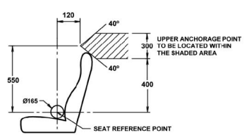
Figure 1 Location of upper anchorages
Anchorages must be provided to suit the seatbelts required by ADR 4/.. They must be positioned so that the seatbelt webbing is able to function properly, without rubbing against any sharp edges. The upper anchorage is to be located within the shaded area shown in Figure 1.
The upper anchorage ‘sash location point’ shall be at least 140 millimetres from the seating reference plane (Refer to ADR 5/..) The lower anchorages must be on opposite sides of the centre line of the seating position and located within the shaded area as shown in Figure 2.
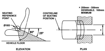
Figure 2 Location of lower anchorages
ADR 5/.. Anchorages for seatbelts
Intent
To specify the requirements for anchorages for seatbelt assemblies so that they may be adequately secured to the vehicle structure or seat and will meet comfort requirements in use.
Requirements
A report prepared by an LVES which demonstrates compliance with ADR 5/.. must be presented or the anchorages shall be designed, located and constructed so that they meet the alternative criterion.
Because seatbelts are generally made to standard lengths it is essential that the lower anchorages be placed in a position behind the seat so as to allow for the buckle of the buckle strap or stalk to be located at the side of the hip of a seated occupant. The buckle must not be allowed to rest on the seated person’s abdomen.
The optimum distance between the lower anchorages of a seatbelt is from 250 mm to 350 mm with the minimum distance being 165 mm. The lower seatbelt anchorages must not be superimposed- ie each seatbelt must be anchored by a separate bolt. Anchorages provided for different seating positions are to be separated by at least 200 mm.
Construction - seatbelt anchorages
All anchorages must be able to withstand a force of at least 10 kN applied for not less than 30 seconds along the direction of the line of the seatbelt. Under test conditions, some deformation is permitted but the anchorage must not pull away from the structure.
Proof of the strength of anchorages shall be by calculation, physical testing or where applicable in accordance with the alternative criterion.
Alternative criterion
When anchorages are located in vehicle floors, parcel shelves or other areas of the vehicle made from sheet metal, steel backing plates (approximately 75 x 50 x 3 mm) are normally adequate.
The size of the seatbelt anchorage backing plate depends upon the strength of the material to which the anchorage is fastened. The following must be taken into consideration when determining the size of the plate:
a. the thickness of the floorpan, upper body or pillar material
b. the shape of the floorpan, upper body or pillar, whether flat, corrugated, fluted, curved box or composite section
c. the type of material from which the floorplan, upper body or pillar has been constructed - eg steel, aluminium.
The corners of all backing plates are to have a 5 mm minimum radius and edges adjacent to the body are to be chamfered.
The anchor bolts must be tightened to the correct tension using a torque wrench. The bolt must fully engage all the thread of the nut and this may mean that a longer bolt than that supplied with the seatbelt kit is required. Fine-threaded 7/16” (11 mm) mild steel bolts are usually used. Anchorages must not be fitted through wood or where wood or other nonmetal material is sandwiched between steel.
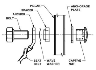
Figure 3 Upper anchorage
Do not fit anchorages in aluminium or fibreglass panels without obtaining specific approval from the engineer. Anchorages and fittings must be protected from corrosion by suitable paint or other anti-corrosive substance. The general construction of anchorages is shown in Figures 3 and 4.
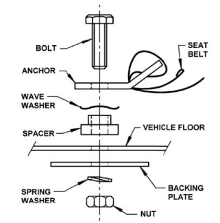
Figure 4 Lower anchorage
ADR 6/..Direction indicator lamps
Intent
To specify the photometric and field of view requirements for direction indicators which will provide adequate warning to other road users of the intention to perform a turning manoeuvre.
Requirements
- The colour of the light emitted shall be amber
- The light emitted from the front and rear lamps shall be visible at all angles between 45 degrees inboard and 80 degrees outboard and 15 degrees above and below the horizontal within these boundaries
- The mounting and visibility of indicator lamps are shown in Figure 5.
ADR 13/.. Specifies that there shall be:
- 2 front-direction indicator lamps
- 2 rear direction indicator lamps
- 2 repeating side direction indicator lamps
- the outside edges of the lamps at the front and rear shall not be more than 400 mm from the outer edge of
the vehicle - the distance between the inner edges of the lamps at the front and rear shall be not less than 600 mm
- the side direction indicator lamps shall not be more than 1800 mm from the front of the vehicle (the side lamps may be combined with the front lamps)
- the lamps at the front and rear shall be not less than 350 mm nor more than 1500 mm above the ground
- the side lamps shall be not less than 500 mm nor more than 1500 mm above the ground
- the direction indicator lamps shall switch on independently of any other lamps
- all direction indicator lamps on one side of the vehicle shall be switched on and off by means of one control and shall flash in phase at a rate of between 60 and 120 times per minute
- the vehicle shall be fitted with audible and or visible indicators for the direction indicator lamps
- the illuminating surface of the front direction indicator lamps must not be less than 40 mm from the illuminating surface of the dipped-beam headlamps or fog lamps if any.
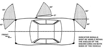
Figure 5 Indicator lamps
ADR 8/.. Safety glazing material
Intent
To specify the performance requirements of material used for external or internal glazing in motor vehicles which will ensure adequate visibility under normal operating conditions with minimum obscuration when shattered, and will minimise the likelihood of serious injury if a person comes in contact with the broken glazing material.
Requirements
Any glass used in windscreens, windows, or interior partitions shall be of safety glass complying with one of the approved standards.
All glass shall carry an indelible mark or marks visible when the glass is fitted in the vehicle. The mark or marks shall identify the type of glass and the relevant standard to which the glass conforms.
The windscreen used shall meet the primary vision area requirements which allow an average driver to see:
- upwards at 10 degrees to the horizontal
- downwards to the roadway 11 metres ahead of the vehicle
- 56 degrees to the left
- 15 degrees to the right of a horizontal line passing through the right eye of the driver which is parallel to the vehicle's centre line.
The primary vision area requirements are shown in Figures 6 and 7.
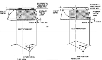
Figure 6 Horizontal elevation
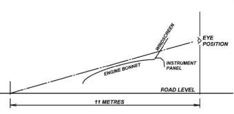
Figure 7 Side view
The visual light transmission of a windscreen in the primary vision area (as defined in ADR 8/..) must not be less than 75% . It is permissible to have a narrow tinted band across the top of the windscreen which is outside the primary vision area.
Window tinting
For information regarding the legal requirements for window tinting refer to Window tinting.
ADR 10/.. Steering column
Intent
To minimise crushing or penetrating injuries to drivers due to the steering column as a result of a frontal impact.
Requirements
The steering column assembly used in a one-off vehicle shall be identical to the one used in a vehicle approved to ADR 10/.. The steering column assembly comprises the basic steering mechanism, the steering wheel, the associated horn actuating mechanism, and trim hardware.
The steering shafts and associated components between the steering column and steering box may also affect compliance with ADR 10/.., consequently the manner of installation is subject to approval.
Optional steering wheels tested to ADR requirements on the column assembly will be accepted.
A motor vehicle must not have a steering control effort in excess of 250 N when the vehicle is operating at a speed not greater than 10 km/h.
The steering control effort is the force exerted by the driver of the vehicle measured at the rim of the steering wheel with any and all power assistance devices operating and no failures being present in the system.
ADR 11/.. Internal sun visors
Intent
To specify requirements for internal sun visors to reduce the injury potential of internal sun visors and the adjacent vehicle structure.
Requirements
If sun visors are fitted to the vehicle they shall be constructed of, or covered with, energy absorption material. Any rigid structure required to support the sun visor or maintain its shape shall be of such dimensions as to limit the likelihood of injury to the head on impact. Any rigid material edge shall have a radius of not less than 3 mm.
ADR 13/.. Installation of lighting and light signalling devices
Intent
Ensure that the installation of lighting and light signalling devices on the vehicle is such that the effective operation of these devices is not impaired.
Requirements
- Main-beam headlamps (ADR46/..)
- Dipped-beam headlamps (ADR 46/..)
- Front fog lamps (ADR 50/..)
- Gas discharge headlamps (ADR 77/..)
- Reversing lamps (ADR 1/..)
- Direction indicator and hazard warning lamps (ADR 6/..)
- Stop lamps (ADR 49/..)
- Rear registration plate illuminating device (ADR 48/..)
- Rear fog lamps (ADR 52/..)
- Front position (side lamps) (ADR 49/..)
- Rear position (side lamps) (ADR 49/..)
- Parking lamps (ADR 49/..)
- Retro-reflectors (ADR 47/..)
- Centre high-mounted stop lamp (ADR 49/.. or ADR 60/..)
- Cornering lamp (ADR 45/..).
Hazard warning signal lamps
The signal shall be given by simultaneous operation of the direction indicator lamps and shall be operated by means of a separate control enabling all the direction indicator lamps to flash in phase. A tell-tale shall be fitted.
The signal shall be able to function even if the device which starts or stops the engine is in a position that makes it impossible to start the engine (ignition off).
ADR 14/.. Rear vision mirrors
Intent
To specify requirements for rear vision mirrors to provide the driver with a clear and reasonably unobstructed view to the rear.
Requirements
Driver’s side mirror
An external rear vision mirror shall be installed on the driver’s side of the vehicle and must provide the driver with a view of a level road surface 11 metres behind the driver’s eyes and 2.4 metres out from the plane represented by the driver’s side of the vehicle. The mirror and mounting shall be free of sharp points or edges.
The mirror shall be adjustable from the driver’s seating position. The mirror may have either a flat or convex reflecting surface. The average radius of a convex mirror is not to be less than 1,200 mm.
Internal rear vision mirror
An internal rear vision mirror shall also be installed except where the design of the motor vehicle does not provide for internal rear vision.
Field of view – an internal mirror shall provide the driver with a view to the rear with an included angle of 20 degrees in the horizontal plane, between left and right, and sufficient vertical angle to provide a view of the road surface 61 metres behind the vehicle extending to the horizon. The line of sight may be partially obscured by seated occupants or by head restraints. Internal rear vision mirrors fitted to the vehicle shall have flat reflecting surfaces.
The internal rear vision mirror mounting shall provide stable support for the mirror, and shall provide for adjustment by tilting in horizontal and vertical directions. If the mirror is subjected to an impact, the mounting shall deflect, collapse or break away without leaving sharp edges.
Passenger side rear vision mirror
If the design of the vehicle does not permit an adequate field of view from the internal mirror an external rear vision mirror shall be installed on the passenger’s side of the vehicle. The passenger side mirror need not be adjustable from the driver’s seating position but shall be capable of adjustment by tilting in both horizontal and vertical directions.
The mirror can be flat or convex. The average radius of a convex mirror is not to be less than 1,200 mm.
ADR 18/.. Instrumentation
Intent
To specify requirements for the provision and location of certain visual indicators.
Requirements
A speedometer shall be fitted which indicates the vehicle speed in kilometres per hour. A speedometer shall not read less that the actual speed of the vehicle. The speedometer must be installed so that its indication is readily visible to the driver when seated in the normal driving position.
An odometer shall be fitted which shall indicate the distance travelled in one-kilometre units or less from 1 to 999,999 kilometres with an accuracy of +/- 4%.
The display of information presented by the visual indicators in the following list shall, if fitted to the vehicle, meet the location requirements shown in Figure 8.
a. Speedometer
b. Direction indicator tell-tale lamp or lamps
c. High beam indicator
d. Tachometer
e. Oil pressure indicator
f. Odometer
g. Water temperature indicator
h. Service brake failure indicator lamp
i. Battery charge failure indicator
j. Stop lamp failure indicator
k. Fuel level indicator
l. Oil temperature indicator
m. Parking brake indicator lamp
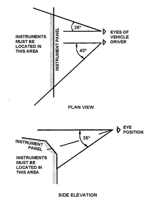
Figure 8 Plan elevation and side elevation
The visual indicators shall be totally visible to the driver with the steering wheel in the straight-ahead position, and with the direction indicator lever in the neutral position, (the steering wheel rim and its supporting arms and attachment do not constitute obstructions).
ADR 21/.. Instrument panel
Intent
To specify requirements for the instrument panel to reduce its injury potential to occupants on impact.
Requirements
The area of the instrument panel that is within the head impact area when impacted, by a given head form and velocity, the deceleration of the head form shall not exceed 80 times the acceleration due to gravity continuously for more than 3 milliseconds. Refer to ADR 69/.. for vehicles incorporating an inflatable supplementary restraint system (airbag).
Alternatively proof of compliance with the alternative criterion.
Alternative criterion
The areas not shown as exempt in Figures 9 and 10 must be covered with high-density energy-absorbing material.
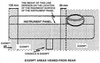
Figure 9 Exempt areas viewed from the rear
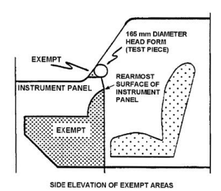
Figure 10 Side elevation of exempt areas
ADR 22/.. Head restraints
Intent
To specify requirements for the design of head restraints so as to limit the severity of injury in the event of rear-end impacts (“whiplash”) and to ensure that the head restraints cannot be adjusted too low.
Requirements
Head restraints are to be constructed and contoured to decelerate horizontal movements of the head without concentrations of load on it.
Head restraints shall be provided for each of the two front outboard seating positions.
The head restraints must be mounted on, or be integral to the seat backs. They may be provided with adjustable mounting but the upper boundary of the impact surface shall not be lower than 700 mm above. Refer to the ‘Seating Reference Point’.
The width of each head restraint shall not be less than 250 mm for use with bench seats and not less than 170 mm for use with individual seats.
The head restraint shall not measure less than 115 mm between upper and lower boundaries.
ADR 23/.. Passenger car tyres
Intent
To specify requirements of strength, construction, and standard pressure/load relationships for passenger car tyres of particular size designations.
Requirements
Each tyre shall be conspicuously labelled on both sidewalls with the following information:
- tyre size designation
- speed category
- tyre carcass construction
- maximum load rating or load index
- identification of the tyre manufacturer
- date of manufacture
- word “tubeless” if applicable.
The labelling shall consist of permanently moulded characters at least 3.8 mm high and 0.25 mm deep if below the background surface, or at least 0.4 mm outstanding, if above the background surface.
Each tyre fitted to the vehicle shall incorporate at least four treadwear indicators approximately equally spaced, each of which provides a visual indication that the tread in its vicinity has a minimum groove depth of 1.25 mm.
ADR 25/.. Anti-theft lock
Intent
To specify requirements for a lock to inhibit unauthorised use of the vehicle and to minimise the possibility of inadvertent application of steering locks to the anti-theft position when the vehicle is in motion.
Requirements
A key-operated protective device shall be fitted to the vehicle to prevent the engine from being started and to prevent the vehicle from being either steered, driven or moved forward under its own power.
This protective device and the components on which it operates shall be so designed that it cannot rapidly and without attracting any attention, be opened, rendered ineffective, or destroyed.
The protective device shall be such that it excludes any risk of accidental operation while the vehicle is in motion which is likely to compromise safety. i.e. It shall not be possible to activate protective devices acting on the steering, transmission or gear shift control without first setting the engine control to a stop condition.
It shall not be possible to activate the motive power of the vehicle by normal means until the protective device has been deactivated.
Alternative criterion
The vehicle shall have a key-operated lock that provides:
- an ‘engine-on’ position that permits the normal functioning of the engine
- an ‘engine-off’ position which prevents the normal functioning of the engine
- an anti-theft position that prevents the normal functioning of the engine and also inhibits unauthorised use of the vehicle.
It shall not be possible to adjust the lock from the ‘engine-on’ position to the ‘anti-theft’ position without passing through the ‘engine-off’ position.
When the key is removed the lock shall be in the ‘anti-theft’ position and it shall be impossible either to steer the vehicle or to engage the forward drive gears or to release a brake without removal or destruction of the device.
ADR 28/.. External noise of motor vehicles
Intent
To specify limits for external noise from motor vehicles in order to limit the contribution of motor traffic to community noise.
Requirements
The vehicle when tested in accordance with the requirements of ADR 28/.. the sound level measured shall not exceed 77 dB(A) for the vehicle in motion test and 90 dB(A) for the stationary test. Alternative criterion Proof of compliance demonstrated by a stationary exhaust noise test in accordance with the National Road Transport Commission – ‘National Stationary Exhaust Noise Test Procedures for In-Service Motor Vehicles.
ADR 29/.. Side door strength
Intent
To specify strength and stiffness requirements for side doors of passenger cars which can be used for occupant access to reduce intrusion into the passenger compartment as a result of a side impact.
Requirements
An engineering report which demonstrates compliance with ADR 29/.. shall be submitted. Alternative criterion Proof of compliance with the technical requirements of S3 and S4 of FMVSS 214 – 35 F.R. 16801, October 30, 1970 Side Door Strength – Passenger Cars as amended by FMVSS 214-58 FR 14169 is required to be submitted.
Note: ICVs are not exempt from ADR 29/… and if no side doors are fitted, the design features to meet the intent of ADR 29/… must be included.
ADR 30/.. Diesel engine exhaust smoke emissions
Intent
To limit the opacity of diesel engine exhaust smoke emissions.
Requirements
A diesel engine fitted to an ICV must comply with ADR 30/.. Smoke Emission Control for Diesel Vehicles. ADR 30/.. refers to ECE Regulation 24 Uniform Provisions Concerning:
i. the approval of compression ignition (C.I.) engines with regard to the emission of visible pollutants
ii. the approval of motor vehicles with regard to the installation of C.I. engines of an approved type
iii. the approval of motor vehicles equipped with C.I. engines with regard to the emission of visible pollutants by the engine
iv. the measurement of the power of C.I. engine.
The diesel engine shall have affixed to it a durable, legible label that indicates that the engine was manufactured to comply with ADR 30/...
The label shall be plastic or metal and shall be bonded, welded, riveted, or otherwise securely attached to a part of the engine necessary for normal engine operation and not normally requiring replacement during engine life. The label shall be in a position in which it can be read after installation in the vehicle.
The engine, as installed in the vehicle, shall be adjusted to the manufacturer’s specifications.
Any cold-starting device shall be designed so that it cannot be brought into or retained in operation when the engine is running normally.
The vehicle shall be equipped with a stopping device which is operated by the vehicle’s ignition switch.
ADR 31/.. Hydraulic brake systems for passenger cars
Intent
To ensure safe braking under normal and emergency conditions for vehicles equipped with hydraulic service brakes.
Requirements
If the vehicle has a hydraulic braking system it shall have:
- a control for the service brake system which is readily accessible to the driver in the normal driving position
- a parking brake system such that in the applied position retention is affected by mechanical means. The control by which the system is actuated is to be readily accessible to the driver in the normal driving position
- one or more service brake failure indicator lamps and a parking brake indicator lamp. The diesel engine shall have affixed to it a durable, legible label that indicates that the engine was manufactured to comply with ADR 30/...
Alternative criterion
Fade test
With the vehicle unladen, fifteen deceleration modes must be conducted in accordance with ADR 31/00 but from a minimum initial speed of 60km/h, such that the sustained deceleration is not less than 4.5 m/s2 for each mode and the distance between successive brake applications is not more than 250 metres or the maximum interval between successive applications is not more than 25 seconds.
The pedal effort as specified in ADR 31/00 must not be exceeded. Refer to the Brake system test procedure.
Effectiveness test
Immediately upon completion of the fade tests, two effectiveness tests must be conducted in accordance with item 7 of ADR 31/00 - ie third effectiveness test.
If the instantaneous deceleration is measured instead of the average deceleration, the deceleration shall not be less than 0.89g for any one of the two stops.
If the above test requirements are met with a pedal effort of less than 150 Newtons the Minimum Pedal Effort Test in accordance with the ADR 31/00 must be conducted.
Refer to the Brake system test procedure.
ADR 34/.. Child restraint anchorages and fittings
Intent
To specify requirements for child restraint anchorages and child restraint anchor fittings to provide for the connection of standard attaching clips so that child restraints may be adequately secured to the vehicle.
Anchorages
Each rear seating position must have either a ‘Child Restraint Anchor Fitting’ or a mounting point for one.
The ‘Child Restraint Anchor Fitting’ is the attachment point for the ‘Attaching Clip’ of a child restraint system and is usually bolted or welded to the structure of the vehicle.
Each anchorage shall be so designed and located that:
a. no items need to be removed to gain access to the anchorage, other than closure plugs, and items that are removable without the use of tools
b. clearance is provided to allow the installation of the child restraint anchor fitting and for the latching and unlatching of the attaching clip to the child restraint anchor fitting without the use of tools
c. it is within 40 mm of the centre line of the seating position
d. it is rearward of the seat backrest
e. information including either a photograph or a diagram regarding the location of each ‘Child Restraint Anchorage’ shall be specified in the vehicle handbook or otherwise supplied with the vehicle.
The information shall include:
WARNING: Child restraint anchorages are designed to withstand only those loads imposed by correctly fitted child restraints. Under no circumstances are they to be used for adult seatbelts or harnesses.
Details on the thickness (and number) of ‘spacers’ required at each ‘Child Restraint Anchorage’ location and the correct method of installation of ‘Child Restraint Anchor Fitting(s)’. See Figure 11.
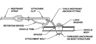
Figure 11 Typical child restrain anchorage assembly in a vehicle
Construction – Child restraint anchorages
All anchorages are to be tested simultaneously and each anchorage must be able to withstand a force of at least 3.4 kN.
The direction of the test load shall be within 20 degrees of the “design line of action” of the child restraint anchorage fitting and not more than 5 degrees to the left or right of the longitudinal axis of the vehicle.
Under test conditions, some deformation is permitted, but the anchorage must not pull away from the structure.
Proof of the strength of anchorages shall be by calculation, physical testing or where applicable in accordance with the alternative criterion.
Alternative criterion
Child restraint anchorages located through a sheet metal section of the vehicle body such as the rear parcel shelf can be constructed by using 50 x 50 x 3 mm steel backing plates, or plates of equivalent size and stiffness with a nut permanently attached to the underside of the plate.
The corners of backing plates shall have a minimum radius of 5 mm and the edges adjacent to the sheet metal shall be chamfered.
ADR 37/01 Emission control for light vehicles
Intent
To limit fuel evaporative emissions and exhaust emissions from motor vehicles in order to reduce air pollution, and to require new vehicles to be manufactured to operate on unleaded petrol.
Requirements
Vehicle to be tested in accordance with the requirements of ADR 37/01 or evidence to be submitted to show that the vehicle complies with the alternative criterion.
Alternative criterion
The engine fitted to the vehicle shall be designed to use unleaded petrol or Liquefied Petroleum Gas (LPG) as a fuel.
The engine must remain standard as manufactured and incorporate all design features and components originally fitted to that engine.
In addition, the vehicle is required to retain any other associated components of the system such as the catalytic converter.
Overseas-sourced engines will be accepted provided that the engine is manufactured to a standard equivalent to ADR 37/01.
Every vehicle shall be so constructed that crankcase gases are not permitted to escape into the atmosphere.
A label of durable material that includes the engine tune-up specifications shall be permanently affixed in the engine compartment. The label may be a copy of the original donor engine label.
In the case of vehicles operating on petrol, an Evaporative Emission Control System which will prevent vaporised fuel from the fuel system from being emitted into the atmosphere shall be fitted.
If the engine is modified away from its standard specifications then the vehicle must be tested to ADR 37/01 or by an IM240 emission testing facility or by an alternative test acceptable to DIT.
ADR 42/.. General safety requirements
Intent
To specify design and construction requirements to ensure safe operation of vehicles.
Requirements
Bonnet latching
Any movable body panel forward of the windscreen that serves to cover an engine, luggage, storage or battery compartment must be provided with a latch system.
A panel opening from the front which in any open position partially or completely obstructs a driver’s forward view through the windscreen shall be provided with a second latch position on the latch system or with a second latch system.
Diesel engines
A locking device shall be provided which prevents the engine from being started by any accidental or inadvertent means. (The locking device must act on the engine and prevent it from starting, should it be cranked by accidental means).
Steering system
The centre line of the steering control must not be located to the left of the centre line of the vehicle.
Any component of the steering system which is essential to the steering operation shall be designed to transmit energy by mechanical means only.
Failure of any non-mechanical component of the steering system must not prevent effective steering of the vehicle.
Standard controls for automatic transmission
All motor vehicles equipped with an automatic transmission shall be fitted with a starter interlock that renders the engine starter inoperative when the transmission control lever is in any forward or reverse drive position.
Electrical wiring, connections and installations
The wiring of electrical equipment other than the high-tension ignition wiring shall:
- be supported at intervals of not more than 600 mm
- be insulated at joints
- be located in such a position that it cannot become overheated, cannot contact moving parts nor constitute a fire hazard owing to its proximity to the fuel system
- be protected from chafing. The edge of all holes in metal through which the wiring passes shall be rolled or bushed with a grommet of rubber or equivalent insulating material.
Exhaust outlets
The exhaust system must not foul any part of the steering, suspension, braking or fuel systems.
The exhaust outlet must not extend outside the outermost edge of the vehicle.
If any part of the exhaust system is not underneath the vehicle and can come into contact with people, it must be shielded.
The vehicle must have at least 100 mm ground clearance.
External or internal protrusions
No vehicle shall be equipped with:
- any object or fitting, not technically essential to the vehicle which protrudes from any part of the vehicle so that it is likely to increase the risk of bodily injury to any person
- any object or fitting technically essential to such vehicles unless its design, construction and conditions and the manner in which it is affixed to the vehicle are such as to reduce to a minimum the risk of bodily injury to any person any object or fitting which, because it is pointed or has a sharp edge, is likely to increase the risk of bodily injury to any person
- any bumper bar the end of which is not turned towards the body of the vehicle to a sufficient extent to avoid any risk of hooking or grazing.
Field of view
A motor vehicle must not be constructed in a manner that prevents the driver from having an adequate view of traffic on either side of the vehicle and in all directions in front of the vehicle to enable the vehicle to be driven safely.
No passenger seating position may be more than 100 mm in front of the driver's seating position when both seats are in the rear position of adjustment.
No motor vehicle must be constructed with a passenger seating position at the right-hand side of the driver.
Wheel guards (mudguards)
The vehicle must be provided with a wheel guard, part of the bodywork, mudguards etc that shall be so designed as to protect other road users, as far as practicable, against thrown-up stones, mud, ice, snow and water to reduce for those users the dangers due to contact with the moving wheels.
The wheel guards must meet the following requirements when the wheels are in the straight-ahead position:
- In the part formed by radial planes at an angle of 30 degrees to the front and 50 degrees to the rear of the centre of the wheel - ie the part of the mudguard between D and E in Figure 12, the overall width (q) of the wheel guards must be at least sufficient to cover the tyre ‘Section Width’ (b) of the tyres fitted to the vehicle, taking into account the extremes of tyre/wheel combinations that may be fitted to the vehicle.
- The rear of the wheel guards must not terminate above a horizontal plane 150 mm above the centre of the wheel and the intersection of the edge of the wheel guards with this plane (point A, Figure 12) shall lie outside the centreline of the tyre.
- The contour and location of the wheel guards shall be such that they are as close to the tyre as possible and they shall satisfy the following requirements:
- The lower lip of the outer edge of the guard shall be at least 30 mm deep directly above the centre of the wheel. This depth (p) may be reduced progressively to zero at points D and E.
The wheel guards may consist of several components, provided that no gaps exist between or within the individual parts when assembled.
The wheel guards shall be securely attached. However, they may be detachable either as a unit or in parts.
The front wheel guard itself or in conjunction with other components - eg bumper bars, of the vehicle body or chassis shall prevent direct contact with the upper half of the wheel in a forward collision.
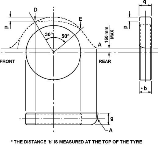
Figure 12 Wheel guards
Brake tubing and brake hose
Air or vacuum brake tubing and air and vacuum brake hose, flexible and hydraulic power hose between the brake power unit and the master cylinder or its equivalent shall conform to SAE, or other approved standards specified for air/vacuum or hydraulic tubing or hose. Brake tubing and hoses are to be fitted to the vehicle to prevent chafing, kinking or other mechanical damage under normal operating conditions.
Reverse gear
An ICV shall be capable of being operated by the driver from the normal seating position in both forward and reverse directions.
Television and visual display units
All television receivers or visual display units shall be installed so that no part of the image on the screen is visible to the driver from the normal driving position unless:
- the television receiver or visual display unit cannot be operated while the vehicle is moving, or
- the television receiver or visual display unit is a driver’s aid.
Examples of driver’s aid include closed-circuit security cameras, navigational or intelligent highway and vehicle systems (GPS), rear view screens and vehicle monitoring devices.
All television receivers or visual display units and their associated equipment shall be mounted in a position that:
- does not obscure the driver’s vision
- does not impede driver or passenger movement in the vehicle
- is unlikely to increase the risk of occupant injury.
Windows and ventilation
At least half the number of windows shall be capable of being opened or the vehicle shall be provided with an alternative method of ventilation.
Power-operated window systems
Power-operated windows, if fitted shall comply with the requirements of ADR 42/.. Clause 19.3 Power Operated Window Systems. Power-operated windows should not be operational 45 seconds after the ignition is turned off.
Warning devices - audible
No device capable of producing a sound resembling that produced by any siren, repeater horn, bell or whistle shall be attached to an ICV.
A repeater horn is any device which emits an audible sound alternating between different tones or frequencies on a regular time cycle.
Every motor vehicle shall be fitted with at least one warning device capable of giving sufficient audible warning of the presence of the vehicle. It shall give an audible signal having constant amplitude and frequency characteristics. It may be powered by any energy source including compressed air.
A further device may be fitted that emits an intermittent audible signal only when the reverse gear is selected. The audible signal is to warn persons of the proximity of the reversing vehicle and should not be louder than is necessary for this purpose.
Demisting of windscreens
Every motor vehicle having a windscreen must be fitted with a device capable of removing condensed moisture from the inside of the windscreen.
Windscreen wipers and washers
Every motor vehicle having a windscreen must be fitted with a power-driven windscreen wiping system.
Every motor vehicle having a windscreen wiping system must have a windscreen washing system that can direct water onto the windscreen within the area swept by the windscreen wipers.
The device or devices for operating the wipers and washer must be able to be controlled by the driver in the normal driving position.
ADR 43/.. Vehicle configurations and marking
Intent
To specify requirements for vehicle configuration and dimensions.
Requirements
Turning circle
Every motor vehicle shall have a turning circle in either direction, as determined by reference to the extreme outer edge of the tyre track at ground level, not exceeding 25 metres in diameter.
Ground clearance
The ground clearance of a vehicle measured from a horizontal road surface to any point of the underside of the vehicle except the tyres, wheels and wheel hubs shall, with the vehicle in its maximum laden condition be not less than 100 mm.
Note: For vehicles with a wheelbase dimension exceeding 3 m or with a rear overhang exceeding 1.5m refer to ADR 43/..
Overall width
The overall width of a vehicle must not exceed 2,500 mm.
ADR 46/.. Headlamps
Intent
To specify the photometric requirements for headlamps which will provide adequate illumination for the driver of the vehicle without producing undue glare for other road users.
Requirements
Only lamps complying with ADR 46/.. are acceptable. The headlamps shall be suitably handed for right-hand drive and the colour of light emitted shall be white.
Headlamps shall be so designed and made, that in normal use despite the vibration to which they may then be subjected, their satisfactory operation continues to be ensured.
The components by which the filament globe is fixed to the reflector shall be so made that, even in darkness, the globe can be fixed in no position but the correct one.
The headlamps shall be so made that they give adequate illumination without dazzle on the passing beam and good illumination on the driving beam.
ADR 13/.. specifies that the vehicle shall have:
- two or four main-beam headlamps positioned at the front of the vehicle and fitted in such a way that the light emitted does not cause discomfort to the driver either directly or indirectly through the rearview mirrors or other reflecting surfaces of the vehicle
- the outer edges of the illuminating surfaces of the main-beam headlamps must not be closer to the outer edge of the vehicle than the outer edges of the illuminating surface of the dipped-beam headlamps
- the main-beam headlamps may be switched on either simultaneously or in pairs. For changing over from the main beam to the dipped beam all main-beam headlamps shall be switched off simultaneously
- a circuit-closed main-beam headlamp tell-tale the colour of which shall be blue
- two dipped-beam headlamps positioned at the front of the vehicle with the outer edges of the illuminating surfaces being not more than 400 mm from the extreme outer edges of the vehicle and with the inner edges of the illuminating surfaces being not less than 600 mm apart
- the lower edge of the illuminating surfaces shall be not less than 500 mm above the ground and the higher edges not more than 1200 mm above the ground
- the dipped beam may remain switched on at the same time as the main-beams
- the control for changing over to the dipped beam shall be a hand or foot-operated switch within reach of the driver in the normal driving position. The dipped beam and main-beam headlamps may be grouped together or with other front lamps.
ADR 47/.. Retro-reflectors
Intent
To specify the dimensional, photometric and stability requirements for retro-reflectors which will ensure that they effectively warn of the presence of the vehicle and continue to do so in normal use.
Requirements
Retro-reflecting devices must be so constructed that they function satisfactorily and will continue to do so in normal use.
The components of retro-reflecting devices must not be capable of being easily dismantled and the retro-reflecting optical units must not be replaceable. The outer surface of retro-reflecting devices must be easy to clean and so it must not be a rough surface. Only complying reflectors will be accepted.
The shape of illuminating surfaces of retro-reflecting devices must fit within a 200 mm diameter circle. The shape of the illuminating surfaces must be simple and not easily confused at normal observation distances with a letter, number or triangle. The colouring of retro-reflecting optical units by means of paint and varnish is not permitted.
ADR 13/.. specifies that:
- a vehicle shall have two or more rear retro-reflectors (non-triangular) affixed at the rear of the vehicle with the outer edge of the illuminating surface being not more than 400 mm from the extreme outer edge of the vehicle
- the retro-reflectors shall not be less than 250 mm nor more than 900 mm above the ground
- they shall be visible in the horizontal plain up to 30 degrees on either side of the centre and up to 15 degrees above and below the horizontal
- the illuminating surface of the retro-reflectors may have parts in common with any other red lamp situated at the rear
- the rear retro-reflectors shall be red.
ADR 48/.. Rear registration plate illuminating devices
Intent
To specify the lighting requirements for rear registration plate illuminating devices which will ensure that the rear registration plate is adequately illuminated.
Requirements
The light of the lamp used in the illuminating device must be sufficiently colourless not to cause any appreciable change in the colour of the registration plate.
ADR 13/.. specifies that:
- the vehicle shall have a rear registration plate lamp so positioned that it will illuminate the site of the registration plate
- the field of visibility of the illuminated surface shall be 5 degrees above and below the horizontal and 30 degrees to either side.
The South Australian Road Traffic (Light Vehicle Standards) Rules 2018 require that the number plate can be read at night at a distance of 20m from the rear of the vehicle.
ADR 49/.. Front and rear position (side) lamps, stop lamps and end-outline marker lamps
Intent
To specify the photometric requirements for vehicle light-signalling devices which will signal to other road users the position, orientation and movement of the vehicle without producing undue glare for other road users.
Requirements
Front position lamps
ADR 13/.. specifies that:
- the vehicle shall have two front position (side) lamps which shall emit a white light
- they shall be so positioned at the front of the vehicle that the outer edges of the illuminating surfaces are not more than 400 mm from the extreme outer edges of the vehicle
- they shall be not less than 350 mm nor more than 1500 mm above the ground
- they shall be visible at all horizontal angles between 45 degrees inboard and 80 degrees outboard and at all vertical angles between 15 degrees above and below the horizontal.
Rear position lamps
ADR 13/.. specifies that:
- the vehicle shall have two rear position (side) lamps which emit a red light
- they shall be so positioned at the rear of the vehicle that the outer edges of the illuminating surfaces are not more than 400 mm from the extreme outer edges of the vehicle
- they shall be not less than 350 mm nor more than 1500 mm above the ground
- they shall be visible at all horizontal angles between 45 degrees inboard and 80 degrees outboard and at all vertical angles between 15 degrees above and below the horizontal.
Stop lamps
ADR 13/.. specifies that:
- the vehicle shall have two stop lamps which emit a red light
- they shall be so positioned at the rear of the vehicle that the outer edges of the illuminating surfaces are not more than 400 mm from the extreme outer edges of the vehicle
- they shall be not less than 350 mm nor more than 1500 mm above the ground
- they shall be visible at all horizontal angles between 45 degrees inboard and outboard and at all vertical angles between 15 degrees above and below the horizontal
- the lamps must light up when the service brake is applied. They need not function if the engine control is in the ‘off’ position - ie ‘ignition off’.
ADR 51/.. Filament globes
Intent
To specify the dimensional and photometric requirements for filament globes which will ensure the interchangeability and correct functioning when installed in a lamp.
Requirements
- All filament globes installed in vehicle lamps must comply with the requirements of ADR 51/.. Filament Lamps
Most commercially available automotive light globes will comply with ADR 51/...
ADR 60/.. Centre high-mounted stop lamp
Intent
To specify requirements for a supplementary ‘Centre High-Mounted Stop Lamp’ on the rear of the vehicle to provide an additional indication to other road users, that the driver of the vehicle is applying the service brakes.
Requirements
The colour of the light emitted shall be red. The lamp shall:
- have an effective projected luminous area of not less than 30 square centimetres
- not contain symbols, letters or characters other than those necessary for part number, manufacturer’s identification and/or approval number identification
- provide access for convenient replacement of the globe without the use of special tools
- provide a steady warning light
- not be ‘grouped’ with any other lamp
- not be combined with any other lamp or reflective device
- not be reciprocally incorporated with any other lamp * be illuminated when the service brakes of the vehicle are applied.
The lamp is to be mounted such that it is:
- in width - on the vehicle’s median longitudinal plane
- in height - either not more than 150 mm above the bottom edge of the rear window or not less than 850 mm above the ground
- facing rearward
- if the lamp is mounted inside the vehicle it shall be shrouded to the glass, or other means shall be provided to minimise reflections from the light of the lamp upon the rear window glazing that might be visible to the driver when viewed directly, or indirectly, in the rear vision mirror.
ADR 61/.. Vehicle marking
Intent
To specify requirements for vehicle marking.
Requirements
Every vehicle shall have a unique Vehicle Identification Number (VIN). The VIN for an ICV is issued by DIT, Vehicle Standards, and must be applied to the vehicle in accordance with the instructions contained in the ‘Statement of Requirements’ for the vehicle. The ‘Statement of Requirements’ is also issued by Vehicle Standards and must accompany the vehicle when it is presented for its roadworthy Inspection.
Engine number
An identification number shall be legible and permanently stamped on the main component of the engine at the time of its manufacture and shall be located where it can readily be seen when the engine is installed in the vehicle.
Registration plates
Provision shall be made for mounting a registration plate that is to be affixed to the front and rear of the vehicle so that no part of the registration plate will be more than 1300 mm from the ground.
No part of the vehicle, including any production options or equipment, must be located to obscure any part of the registration plate(s).
Dynamic occupant protection and other safety systems
The following ADRs specify dynamic occupant protection requirements and normally require destructive crash testing using crash test dummies to verify compliance:
- ADR 69/.. Full frontal impact occupant protection
- ADR 72/.. Dynamic side impact occupant protection
- ADR 73/.. Offset frontal impact occupant protection
- ADR 85/.. Pole side impact performance
Other safety systems are
- ADR 88/.. Electronic stability control
- ADR 89/.. Brake assist systems
- ADR 98/.. Advanced emergency braking for passenger vehicles
- ADR 99/.. Lane departure warning systems
- ADR 108/.. Reversing technologies
- ADR 113/.. Acoustic vehicle alerting systems for quiet road transport vehicles
Individually Constructed Vehicles (ICVs) are not required to demonstrate compliance with these ADRs due to the complex, costly, and destructive nature of the testing involved, provided the applicable ICV requirements and conditions are met.
However:
- Vehicle designers should give a high priority to occupant protection and crash survivability and incorporate design features that are likely to minimise injury to occupants in the event of a crash.
- A metal placard or permanent waterproof label must be fitted to the vehicle warning occupants that the vehicle has not been tested in accordance with ADRs requirements relating to Occupant Protection, ESC and Brake Assist Systems. The warning must contain the wording shown in Figure 13 and be fitted in the passenger-side door aperture or another position where it will be clearly visible when entering or while seated in the vehicle.
- The warning displayed on the placard/ label must also be contained in the vehicle handbook or otherwise be supplied with the vehicle.
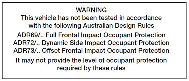
Figure 13 Warning label
Airbags
Due to the highly technical and complex nature of airbag design and the associated calibration necessary to ensure proper operation without false deployment, it is not recommended to fit airbags to ICVs.
Gas discharge headlamps
Gas discharge headlamps may be fitted to an ICV but are inherently complex, expensive and subject to additional requirements beyond that of regular headlamps. Refer to ADR 13/.. Installation of Lighting and Light Signalling Devices on other than L-Group Vehicles and ADR 77/.. Gas Discharge Headlamps
Vehicle Standards reference: MR840.