On this page
Modifications can dramatically reduce the strength of a vehicle's structure, and additional strengthening may be required to restore the structural integrity. This may result in extra stiffness in certain areas of the chassis but overstressing in others. Consequently, it becomes necessary to demonstrate that the modified vehicle’s beaming and torsional strengths are adequate when compared to the original vehicle and that there are no abrupt changes in the strength and stiffness of loaded sections. An example of a structural alteration is the changing of a vehicle's wheelbase measurement or the removal of a vehicle roof section.
This page contains a test procedure in terms of vehicle structural analysis and is intended as a guide for those who wish to undertake structural alterations to a vehicle or are building a one-off new construction vehicle. As such, the results of testing may be taken only as a guide to the structural integrity of the vehicle. For this reason, absolute values should not be derived from the results.
When considering vehicle modifications, where possible it will be necessary to test the unmodified vehicle before commencing work, in order to have valid values for comparison.
It remains the modifier’s responsibility to ensure that the structure and safety of the vehicle are not prejudiced by the modifications. Any subsequent structural failure of the vehicle in service as a direct consequence of the modifications shall be the responsibility of the modifier.
Test procedure
1. Vehicle setup
All hinged panels are to be ajar at all times during testing - ie bonnet, boot lid, and doors to be open.
2. Loading
The unmodified vehicle shall be weighed prior to testing to determine its unladen mass. This weighing must be carried out with the fuel tank filled at not less than 75% capacity. Alternatively, an equivalent mass to the specified volume of fuel may be positioned near the fuel tank.
The gross vehicle mass (GVM) of the unmodified vehicle is determined by adding the payload capacity of the vehicle to the unladen mass (or weighed mass). In the case of a passenger-carrying vehicle, the payload shall be 68kg for each seating position.
3. Jig
The vehicle to be tested shall be safely supported for loading up to the specified values. It shall be mounted through the hubs, with its springs and dampers made incompressible or replaced by spacers. Figure 1a and 1b indicate the preferred mounting of the vehicle for beam and torsion tests.
Rear supports must be able to resist the up thrust for the torsion test. Other methods of supporting the vehicle will be considered as long as the support points are not located within the wheelbase.
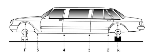
Figure 1a. Typical test rig - side elevation and location of measuring points
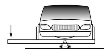
Rollers or similar allow transverse movement of the hinge point as the vehicle rotates.
Note: All hinged panels must be ajar during testing.
Figure 1b. Typical test rig - front elevation
Measurement points
The deflections are to be measured at the points shown in Figures 1a and 1c. Front and rear points are to be measured on the body member as close as possible to the suspension attachment points - approximately on the axle centreline.Measurements on the outside of the mudguards are not acceptable.
Positions 2 and 5 shall be at the extreme ends of the sills or at equivalent positions on the vehicle without door cut-outs.
Positions 3 and 4 shall be approximately equally spaced between points 2 and 5. As an alternative, 3 intermediate positions within the wheelbase are acceptable as a minimum, with similar positioning.
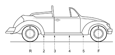
Figure 1c. Typical location of measuring points
Beaming test procedure
Step 1 - With the unmodified vehicle mounted securely, load the vehicle in accordance with Step 3 below to settle the apparatus and check that it is functioning correctly. No readings of deflection need to be taken for this preload.
Step 2 - Remove the loading required in Step 1 above and 'zero' all gauges.
Step 3 - A load equivalent to twice the payload - ie 68kg x 2, shall be applied at each seating position. Other means of distributing an equivalent overall load within the passenger compartment of the vehicle will be considered provided the distribution of the load is similar to that resulting from applying the loads at the seating positions.
Step 4 - Record deflections.
Step 5 - Remove load.
Step 6 - Record deflections again and check that vehicle has returned to substantially the same zero position as recorded in Step 2 above. If there is any significant variation, Steps 2 to 6 must be repeated.
Torsion test procedure
Step 1 - With the unmodified vehicle mounted securely, load the vehicle in accordance with Step 5 below to settle the apparatus and check that it is functioning correctly. No readings of deflection need to be taken for this preload.
Step 2 - Remove the loading required in Step 1 above and 'zero' all gauges.
Step 3 - Calculate the required turning moment to be applied using the formula: 0.25 x GVM x wheel track. To calculate this, multiply 0.25 x GVM in kg x 9.81 x wheel track in metres, to obtain the turning moment in units of Newton metres (Nm).
Step 4 - Calculate the required loading force at the lever arm position to apply the turning moment determined in Step 3, correctly applying any necessary conversion of units, multiplication by constants etc.
Step 5 - Apply this loading force in a gradual and controlled manner.
Step 6 - Record deflections.
Step 7 - Remove loading.
Step 8 - Record deflections again and check that vehicle has returned to substantially the same zero position as recorded in Step 2 above. If there is any significant variation, Steps 2 to 8 must be repeated.
Modified vehicle test procedure
The modified vehicle is to be tested in the same manner, and with the same loads used above. Where vehicles have changes to the number of seating positions, such as limousines, the original beaming load must be evenly distributed over each seating position. The turning moment applied in the original torsion test is to be reapplied to the modified vehicle.
Data recording
Test data, loadings, etc. can be recorded on the standard test reporting forms below or reports from appropriate software can be used.
A graphical plot of the average of the deflection of the left and right-hand sides at each measuring location along the wheelbase with the applied load, and again with the load removed, shall be provided for both the unmodified and modified vehicle. A plot of each vehicle's angular deflection at each measuring location along the wheelbase with the load applied, and after the load has been removed, shall also be provided.
Beam deflection plots are to be reduced to a zero datum line through points 'R' and 'F' to eliminate the contribution of jig movement, etc. to absolute values. Angular deflections are to be similarly reduced by subtracting the rotation measured at the fixed-end axle line from each absolute rotation value.
Validity of torsion test results
If during a torsion test it is evident that the fixed end rotated by more than 20% of the angular rotation of the end that was being rotated, the test must be repeated. Measures must be taken to reduce any angular rotation of the fixed end to less than 20% of that of the end being rotated before testing recommences.
Acceptable criteria - guidelines
These figures are generally accepted but Vehicle Standards may vary these standards for any vehicle or modification type for which they are shown to be inappropriate.
Convertible and cabriolet vehicles
Beam strength criterion
The average deflection of left and right-hand sides from the datum line 'RF', under the maximum applied load, at any measuring position for the modified vehicle shall not be greater than 1.5 times the deflection recorded for the unmodified vehicle.
Torsional strength criterion
The reduced angular deflections, under the maximum, applied load at any measuring position for the modified vehicle shall not be greater than 1.5 times the angular deflection recorded for the unmodified vehicle at the same measuring position.
Extended wheelbase vehicles
Beam strength criterion
The beaming deflections, reduced to a zero datum line, of the modified vehicle when compared to that of the unmodified vehicle must not have increased in a proportion greater than the proportional increase in wheelbase.
Torsional strength criterion
The ratio of the torsional rigidity of the modified vehicle to that of the unmodified vehicle must not be lower than the ratio of the wheelbase of the unmodified vehicle to that of the modified vehicle.
Modified production vehicles
Modified production vehicles fitted with larger capacity engines should have a torsional stiffness similar to contemporary vehicles fitted with engines of similar output.
Individually constructed vehicles
The structure of the individually constructed vehicle (ICV ) or kit car body/chassis must be such that there are no abrupt changes in the strength and stiffness of loaded sections. Abrupt changes in the section must be avoided as they may produce stress concentrations and result in cracks and fatigue failure. Manufacturers should inform themselves in this respect or seek qualified assistance.
Torsional rigidity should be at least 4,000 Nm per degree over the wheelbase unless the vehicle has been professionally designed to operate at lower stiffness levels.
In any event, the manufacturer of the ICV is responsible for the strength of the completed vehicle.
Vehicle Standards reference: MR810.