On this page
The purpose of this guide is to inform manufacturers and retailers about the safety requirements applying to the design, specification, and fitting of vehicle frontal protection systems (VFPS) to light vehicles on South Australian roads. VFPS includes bull bars, roo bars, and nudge bars.
It provides an appropriate balance between the protection of vehicles from animal strikes and the safety of pedestrians, and other unprotected road users by offering clear guidance to help ensure that the VFPS complies with rule 29A of the Road Traffic (Light Vehicle Standards) Rules—the Light Vehicle Standards.
This information is a companion to Bull bar safety considerations.
Background
For many years, a VFPS has been accepted as an accessory for most vehicle types, often fitted to help protect a vehicle in the event of a crash with an animal, such as a kangaroo, by reducing the potential for damage to the cooling system and leaving the vehicle stranded after an impact.
However, when a poorly designed VFPS is fitted to a vehicle, it can be dangerous to vulnerable road users such as pedestrians and cyclists in the event of a collision.
In addition, the continued development of vehicle technology and ongoing improvements in vehicle safety systems have led to a situation whereby the fitting of a non-compliant VFPS may actually interfere with the sophisticated safety systems designed for modern vehicles.
A great deal of research has been conducted into the possible effects of a VFPS in a collision and ways of optimising their design. This document has been produced following detailed technical investigations. It supports and builds upon the information contained within Australian Standard AS 4876.1-2002 Motor vehicle frontal protection systems Part 1: Road user protection, which primarily addresses the issue of minimising the risk of injury to pedestrians as a result of colliding with a vehicle fitted with a VFPS.
Requirements
Rule 29A of the Light Vehicle Standards applies to vehicles with a gross vehicle mass (GVM) of no greater than 3.5 tonnes that were manufactured after 30 June 2013 and requires VFPS fitted to these vehicles to comply with AS 4876, except for clause 3.2 of the Standard.
Every VFPS must be designed to minimise the risk to pedestrian safety and the likelihood of penetrating into other vehicles in the event of a crash by adhering to the following guidelines.
It is strongly recommended that VFPS fitted all other light vehicles comply with the information on this page.
Initial point of contact
The initial point of contact between the bull bar and the pedestrian in the event of a collision should be as low as possible.
As defined in Diagram 1:
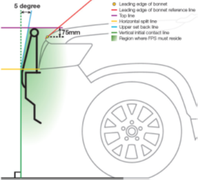
- The VFPS must reside in the green-shaded area.
- The initial point of contact must not be higher than the Horizontal Split Line (yellow line).
- The horizontal split line is coincident with the line used to determine the minimum height of the dipped beam headlamp above the ground on an unladen vehicle which is measured from the bottom of the illuminating surface. All vehicles still need to comply with the ADR height requirements for headlights.
- The upper set-back line (blue line) starts at the junction of the vertical initial contact line (green line) and the horizontal split line (yellow line) and is set back 5 degrees to the vertical.
Diagram 1 - Defined area (shaded green) within which the VFPS profile must reside
As defined in Diagram 2:
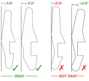
- The structure that joins the VFPS main channel and upper structure or tube is referred to as the ‘upright’. The upright shall not have any lower scuttle bar or lean forward below the initial contact point. The projection of the profile moving down from the initial contact point can move rearward or vertically but not forwards.
Diagram 2 - Examples of acceptable and unacceptable upright profiles
Height of the VFPS
The VFPS upper structure should be designed to be as low as possible to minimise the danger to pedestrians in the event of a collision, as well as minimising the impact on vehicle airflow and non-safety critical functions such as parking cameras and sensors. The top of the VFPS should not protrude above the front of the bonnet line.
The operation of original equipment, such as the headlights or distance sensors (radar etc) must not be affected by the fitting of the VFPS.
As defined in Diagram 1:
- No part of the VFPS can be more than 75 mm above the leading edge of the bonnet when measured at the centre line of the vehicle, as defined by the top line (purple line) in Diagram 1.
- In addition, when the VFPS is fitted to the vehicle, the field of view requirements (see Diagram 4) must continue to be met.
Determination of the leading edge of the bonnet
ANCAP Test Protocol Pedestrian Protection v8.5 (Jan. 2019, p.15) defines the 'Bonnet Leading Edge Reference Line' as shown in Diagram 3.
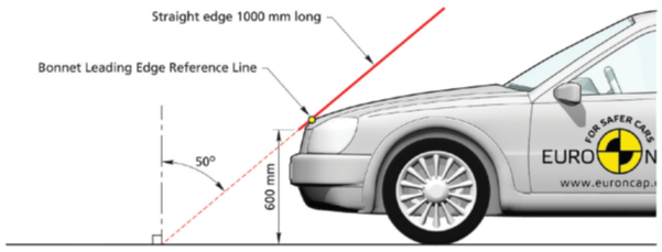
Diagram 3. Determination of the bonnet leading edge reference line
The definition, which can be used as a guide to determine the leading edge of the bonnet, is as provided in UN Regulation No. 127 Pedestrian Safety Performance which lays down requirements for the construction and functioning of motor vehicles and frontal protection systems in order to reduce the number and severity of injuries to pedestrians and other vulnerable road users.
In conjunction with the requirements for top tube height limits, as outlined in Diagram 1, the VFPS top protection structure may have an upward trajectory towards the outer edges of the vehicle to allow clearance for the headlight beams and protection of the leading edge of the bonnet.
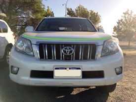
Figure 1. Example of leading edge of the bonnet
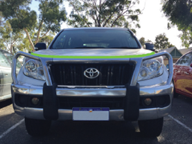
Figure 2. Example of upward trajectory of VFPS
FPS to follow the frontal profile of the vehicle
To minimize the risk of increased pedestrian injury, the whole VFPS must conform to the frontal profile of the vehicle to which it is fitted.
Put simply, the VFPS must follow the shape, in plan view, front view, and side view, of the front of the vehicle.
The side profile of the VFPS must not be any steeper than the side profile of the front of the vehicle. The VFPS must not lean forward.
As defined in Diagram 1:
- The VFPS upper structure must have a minimum rearward rake angle of 5 degrees from vertical.
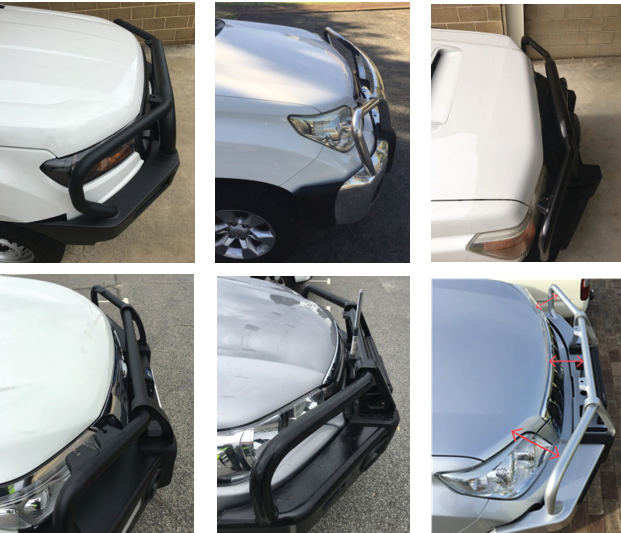
Figure 3. Examples of acceptable VFPS designs
The maximum distance from the leading edge of the bonnet to the inside of the VFPS should not exceed 200 mm where practicable. Suggested measurement positions are shown by the red arrows above.
Dangerous projections
Rule 29 of the Road Traffic (Light Vehicle Standards) Rules prohibits dangerous projections and sharp corners. The VFPS must be designed so as to prevent the hooking or grazing of other road users:
- Exposed edges need to be chamfered and free of burrs or sharp edges.
- Forward-facing edges must have radii not less than 5 mm.
- Open-ended frame members are not permitted.
Where the front bumper of the vehicle is removed to allow a VFPS to be fitted, the design of the VFPS must not cause any dangerous projections, for example by exposing sharp chassis rail edges and components such as bolt threads that were previously masked by the OEM bumper bar, air dam or a spoiler. Brush rails (side rails, brush guards) must not have sharp edges or protruding bolt heads.
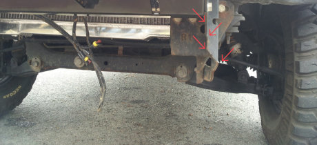
Figure 4. Example of exposed edge creating a dangerous projection
Recovery points and brackets should be fitted at a minimum distance of 100 mm behind the front face of the VFPS and be free of burrs and sharp edges.
All new model vehicles manufactured from 1 July 2019 must comply with the requirements of ADR 92/00 External Projections.
VFPS in conjunction with other vehicle modifications
A vehicle that is compliant when fitted with a VFPS may no longer comply if the vehicle is subsequently modified.
For example, the combined effect of a vehicle suspension lift and the fitting of a VFPS may compromise compliance with ADR requirements for wheel coverage.
Contact the Department for Infrastructure and Transport’s Vehicle Standards Team if you require any further advice on vehicle modifications.
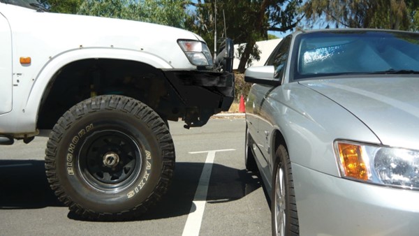
Figure 5. Example of a non-compliant vehicle
Attachments and attachment points on a VFPS
It is acceptable to have attachment points fixed to a VFPS for items such as aerials and driving lights provided they are only placed rearward of the front face of the VFPS in a manner that prevents them from becoming dangerous projections.
Similarly, fishing rod holders may only be fitted if they do not protrude forward of the front face or above the top bar of the VFPS to which they are fitted and do not become a dangerous projection.
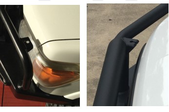
Figure 6. Examples of acceptable attachment points on a VFPS
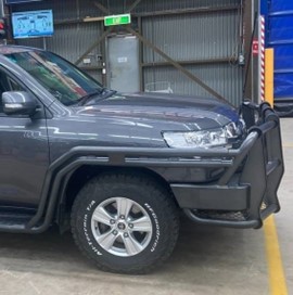
Figure 7. A brush guard or side rail
A VFPS may not increase the width of the vehicle on which it is installed. Brush rails are considered to be attachments and they are not included when measuring the width of a VFPS provided they are as close as possible to the body of the vehicle. Mirrors are not included when measuring the width of a vehicle.
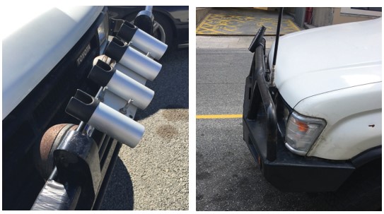
Figure 8. Rod holders mounted as shown are dangerous projections and are not acceptable
Vehicle lighting
The installation of a VFPS may result in the existing lighting being obscured and consequently prevent the vehicle from complying with ADR 13/00 Installation of Lighting and Light Signalling Devices on other than L-Group Vehicles.
Where ADR lighting requirements are not satisfied, additional ADR-compliant lamps must be fitted.
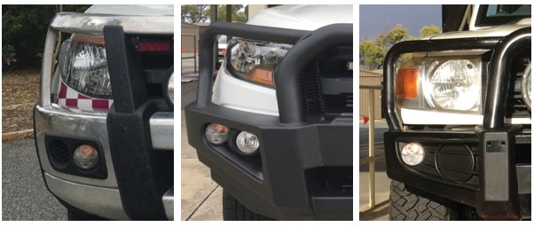
Figure 9. Examples of acceptable additional lighting on a VFPS
Field of view
Any VFPS, together with any attachments, must not reduce a driver’s ability to safely drive the vehicle to which it is attached.
When sitting in the driver’s seat with the seat located at its rearmost position, it shall be possible to see the surface of the road 11 metres in front of the driver’s eye looking across the top of the VFPS as shown below.
For the purposes of this requirement, the driver’s eye position can be taken as being a point 730mm above and 270mm forward of the junction of the seat cushion and squab (back) with the seat in its lowest and rearmost position.
Driving lights and other accessories that will obscure the driver’s field of view must not be attached to the top rail of a VFPS.
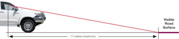
Diagram 4. Field of view
Front axle load rating
The maximum front axle weight of the loaded vehicle fitted with a VFPS and any accessories must not exceed the manufacturer’s front axle load rating.
Manufacturer’s safety equipment
Any VFPS fitted to a vehicle must not render ineffective the operation of any safety features fitted to the vehicle by the vehicle manufacturer.
Continued compliance with all Commonwealth and State requirements
Any vehicle fitted with a VFPS must continue to comply with all applicable Australian Design Rules and State requirements.
Approval requirements
Any VFPS that complies with the requirements of this information is considered to be an acceptable vehicle modification that does not require the owner of the vehicle to obtain an exemption from the Department for Infrastructure and Transport (DIT). Manufacturers or suppliers who fit a complying VFPS, therefore, do not need to seek prior approval before fitting these to road vehicles.
Any VFPS that does not comply with this information risks failing a vehicle inspection or being issued with a defect notice by on-road enforcement officers and may be required to be removed from the vehicle.
If there is any doubt that the fitting of a particular VFPS design may not comply with this information, suppliers or manufacturers must contact the Department for Infrastructure and Transport’s Vehicle Standards Team before fitting the VFPS.
Selection of a suitable VFPS
When purchasing a VFPS, consumers are strongly advised to select a design of VFPS that not only meets the design requirements of this information but is suitable for their driving requirements.
A style of VFPS such as a nudge bar (Figure 10) may be more appropriate to a vehicle that spends most of its time in the Metropolitan Area. For vehicles that travel extensively on country roads, the more traditional bull bar design (Figure 11) may be more suitable.
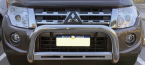
Figure 10 - Example of a nudge bar
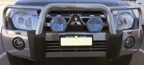
Figure 11 - Example of an urban bull bar
Fitting of VFPS to ADR 69/00 and ADR 73/00 vehicles
Australian Design Rule 69/00 Full Frontal Impact Occupant Protection and Australian Design Rule 73/00 Offset Frontal Impact Occupant Protection set minimum levels of occupant protection, as determined by crash testing. Depending on the design and application, a VFPS may positively or negatively affect occupant safety in a crash situation.
ADR 69
ADR 69 affects the following vehicles:
- from 1 July 1995, all new model MA vehicles (passenger cars)
- from 1 January 1996, all MA vehicles (passenger cars)
- from 1 January 1998, all new model MB vehicles (forward control passenger vehicles), and all new model MC vehicles (off-road passenger vehicles)
- from 1 July 1998 for new model NA1 vehicles (light goods vehicles)
- from 1 January 2000 all MB vehicles (forward control passenger vehicles), and all MC vehicles (off-road passenger vehicles)
- from 1 July 2000 all NA1 vehicles (light goods vehicles).
ADR 73
ADR 73 affects the following vehicles:
- from 1 January 2000, all new model MA vehicles (passenger cars) and with a gross vehicle mass (GVM) of less than 2.5 tonnes
- from 1 January 2004, all MA vehicles (passenger cars) and with a GVM of less than 2.5 tonnes.
For these vehicles, VFPS manufacturers will need to provide evidence that the fitting of their product does not interfere with the intent of the occupant protection provisions specified in ADR 69 and ADR 73 eg- by conducting physical tests or computer simulations.
Airbags may be fitted by vehicle manufacturers in order to comply with ADR 69 and ADR 73 or as an additional safety feature at the manufacturer’s discretion. The triggering methods used to deploy the airbags vary greatly in complexity between manufacturers. The fitting of a VFPS to the front of a vehicle may have an unknown effect on the deployment characteristics of an airbag. VFPS manufacturers will need to demonstrate that the fitting of their product does not adversely interfere with the triggering of the airbag system.
Research to date indicates that the strength of the mounting points is one of the most significant parameters of the VFPS’s potential to interfere with the vehicle’s crashworthiness. The research has shown that carefully designed mounting points result in little or no effect on the vehicle's ability to satisfy ADR 69/ and ADR 73/.
VFPS manufacturers should acquaint themselves with this information and ensure that their VFPS designs comply with these requirements. Manufacturers should utilise the services of a professional engineer if required to assist them in interpreting this data and applying it to their designs.
If the VFPS can be fitted with brush guards, then any testing should be undertaken with them fitted.
VFPS labelling
Each VFPS shall have a durable plastic or metal plaque permanently attached by bonding, riveting, welding, drive screws, or a durable integral label, on a surface of the bar such that the label can be read when the VFPS is attached to a vehicle and located where it will not sustain environmental damage. The labelling shall comply with the requirements of AS 4876.1-2002 Motor vehicle frontal protection systems Part 1: Road user protection, Section 1.4 – Marking, that is:
The plaque or label or permanent marking shall display the following information in permanent, legible, upper and lower case, black characters in English not less than 4 mm high:
(a) The name and address of the manufacturer, supplier, or importer, or the manufacturer’s trademark, if made in Australia.
(b) A description indicating the make, model, type, and year(s) of manufacture of the motor vehicle for which the VFPS is designed.
(c) An identification code that permits the manufacturer, supplier, or importer to identify a specific production batch.
(d) The statements, ‘This product or its fixing must not be modified’, ‘No accessory or fitment shall project forward of this product’s forward profile’, and ‘Do not use this product in any other motor vehicle for which it is not designed.’
Non-compliant VFPS designs
The following VFPS designs do not meet the requirements.
[Fig numbers changed to match sequence]
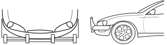
Figure 12. VFPS does not follow the front profile of the vehicle, the VFPS is too high
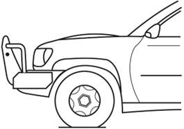
Figure 13. VFPS leans forward on the vehicle, the VFPS is too high
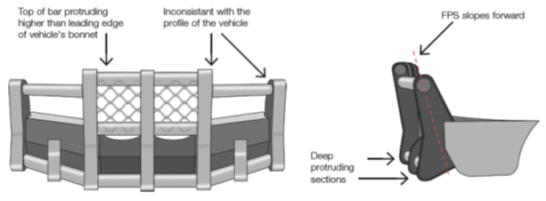
Figure 14. VFPS has an unacceptable upright profile, the VFPS is too high
Vehicle Standards reference: MR1505.