On this page
Permanently attached load-carrying devices become part of the vehicle and are not a load.
It is a legal requirement that anything attached to a vehicle must be designed to minimise the risk of any injury to persons coming into contact with the vehicle.
Loading frames are considered to be part of the vehicle body, not a load. This information outlines the construction criteria for:
- external load racks on light vehicles for the carriage of glass and other panel-type products
- lighting and rear vision mirrors where there is an increased overall vehicle width.
It is strongly recommended that external loading frames are only installed on cab chassis vehicles in place of a full-width tray or tub body as this reduces the side overhang and enables the load to be as close to the ground as possible.
While not prohibited, loading frames mounted on the outside of tub bodies and vans are not supported by this guide.
Loading frame
The loading frame must comply with the following:
- The tray top must be as narrow as possible so that the loading frame is as close as possible to the rear wheels.
- The total width of the vehicle, including the loading frame, must be no more than 2.5 metres.
- The foot or baseboard dimensions must be kept as small as possible.
- The loading frame must be angled inward, from no less than 6⁰ or no more than 9⁰ from the vertical, to ensure the stability of the load and assist in safe loading.
- All leading edges must either be radiused, minimum of 2.5 mm radius, returned, finished with a round rod, or protected by suitably shaped moulding.
- All open hollow sections shall be plugged.
- The loading frame must have front shield panels, at least the width of the foot or baseboard, and must cover sharp edges.
- The shield panels must be of sufficient height to render them clearly visible (shields will need to be at least 800 mm in height from the base of the frame).
- Shield panels must begin as close as possible to the vehicle bodywork and be rounded or angled backward by at least 15⁰ (see Figure 1).
- Clamps must be designed with the shortest possible bolt length to reduce the likelihood of injury resulting from dangerous projections.
- T-handle clamp adjusters must not be located below 2 metres from ground level.
- T-handle clamp adjusters located lower than 2 metres from ground level will not be accepted after 1 January 2022.
- While turn wheels may be used in place of T-handles, other clamping devices may be used, provided that they are designed to minimise the risk of injury to any person.
- Where any restraints are used, e.g. clamps or brackets, they must be fitted in a manner so as not to increase the risk of injury to any person.
- All restraints - eg clamps and brackets) must fall within the 2.5 metre maximum width limit.
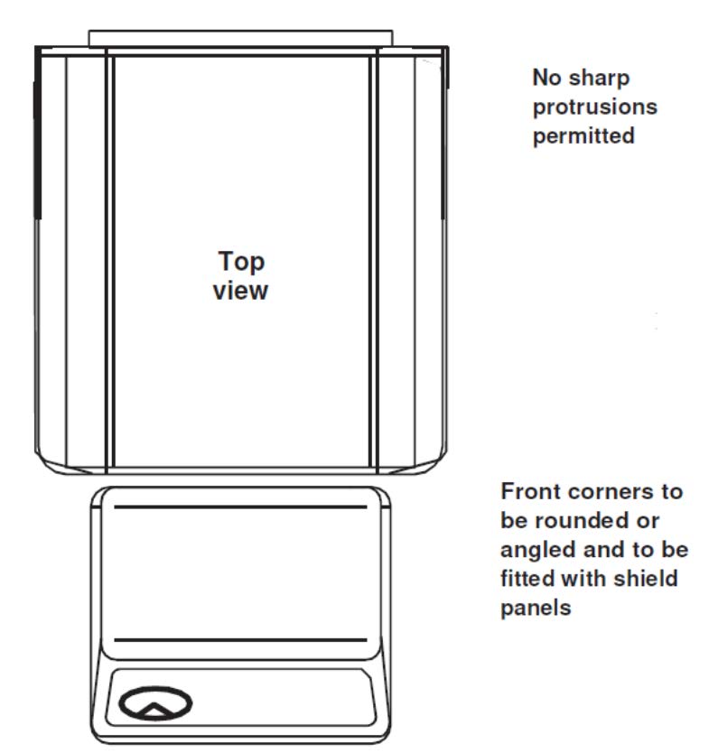
Figure 1. Shield panel
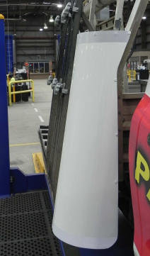
Acceptable loading frame
with turn wheels
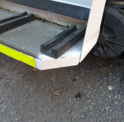
Not acceptable loading frame
Rear vision mirrors
The vehicle must be equipped with both left and right-hand rear vision mirrors conforming to Road Traffic (Light Vehicle Standards) Rules 2018 rule 34, as follows:
- The mirrors must reflect a clear view of the road to the rear and of any following or overtaking vehicles.
- Depending on the height of the shield panels it may be necessary to replace or extend the rear vision mirrors.
- Mirrors may project 150 mm beyond the point of the overall width of the vehicle:
- non-folding mirrors must not project beyond the 2.5 m overall width
- if the mirrors can fold to project not over 150 millimetres beyond the overall width, they may project up to 230 mm beyond the widest part of the vehicle.
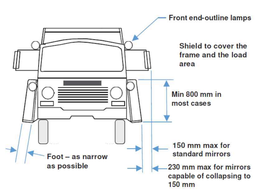
Figure 2. Mirrors
Loading and load restraint
Correct loading and load-restraining techniques are vital to the safe operation of these vehicles.
The frame loads must be balanced from side to side and front to rear. The restraints - eg clamps and brackets, must comply with the performance standards required by the Load Restraint Guide published by the National Transport Commission, as in force from time to time.
With conventional J-bracket clamp bars, the recommended procedure is to wind the turn wheel or T-bar until the pad contacts the glass, then turn the handle a further half-turn. Overtightening risks bowing the bar or breaking the load.
All thrust arms must be engaged to ensure even pressure along the bar.
When not in use it is suggested that the restraints are removed or retracted as much as possible to minimise protrusion.
Lighting
Both front and rear vehicle lighting must conform to the regulatory requirements.
This may involve the relocation of items such as lamps and retroreflectors.
White retroreflectors or retroreflective tape must be installed on the outer edges of the front shield panel.
Red retroreflectors must be installed on the rearward face of the foot or baseboard.
On narrow cab trucks and utilities, the overall body width must not exceed 400mm beyond the outside edge of the headlights, in accordance with the Australian Design Rules (ADRs), whilst staying under 2.5 metres maximum.
Increases in width may be limited by the relative position of the front lamps.
All matching pairs of lamps must be symmetrically mounted, - ie. the same height and distance from the vehicle centreline
The requirements for the geometric visibility of the direction indicator and side-marker lamps are shown in Figures 3, 4 and 5.
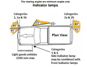
Figure 3. Indicator lamps
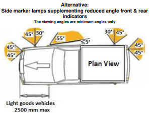
Figure 4. Alternative indicator lamps
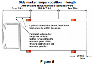
Figure 5. Side marker lamps
The locations of the lights are shown in Figures 6 and 7 and Table 1.
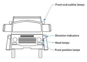
Figure 6. Front view of lamps
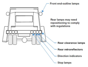
Figure 7. Rear view of lamps
Table 1
| Lamp | Height | Distance apart | Max distance from edge |
|---|---|---|---|
| Headlamp | Not less than 500 mm and not more than 1,200 mm | Not less than 600 mm apart | 400 mm |
| Front position lamp | Not less than 250 mm nor more than 1,500 mm | Not less than 600 mm apart | 400 mm |
| Rear position lamp | Not less than 350 mm nor more than 1,500 mm | Not less than 600 mm apart | 400 mm |
| Direction-indicator lamp | Shall not be less than 350 mm or more than 1,500 mm | Not less than 600 mm apart | 400 mm |
| Stop lamps | Not less than 350 mm nor more than 1,500 mm | Not less than 600 mm apart | 400 mm |
| Rear retro-reflector | Not less than 250 mm nor more than 900 mm (not more than 1,200 mm if grouped with any rear lamp(s), 1,500 mm if the shape of the bodywork makes it impossible to keep within 900 mm or 1200 mm respectively) | Not less than 600 mm apart | 400 mm |
| Front end-outline marker lamp mandatory if wider than 2100 mm | Not be lower than the horizontal plane tangential to the upper edge of the transparent zone of the wind-screen | As close as possible to, but no more than 400 mm from, extreme outer edge | |
| Rear end-outline marker lamp mandatory if wider than 2100 mm | Maximum height is compatible with the requirements relating to the width, design, and operational requirements of the vehicle and to the symmetry of the lamps. | As close as possible to, but no more than 400 mm from, extreme outer edge | |
Note: all dimensions are taken from the edge of the illuminated surface (lens).
For further information on the location of lamps, consult ADR 13/00 Installation of Lighting and Light Signalling Devices on other than L-Group Vehicles.
Vehicle Standards reference: MR1665.